Heater assembly

a space heater and assembly technology, applied in the field of space heaters, can solve the problems of space heaters slipping, overheating, and fire, and causing fire,

Active Publication Date: 2013-09-12
SEBOLT JOSEPH A
View PDF2 Cites 13 Cited by
  • Summary
  • Abstract
  • Description
  • Claims
  • Application Information

AI Technical Summary

Benefits of technology

[0009]The television utilized in the combination device is preferably a wall mountable high definition television (HDTV). The space heater is engaged with the television and a frame is provided around the television and space heater. The combination device preferably is mountable on a wall. The television / space heater combination device is configured to display an image of a burning flame on the television's screen if desired. Preferably, this is accomplished by including a continually playing video loop in the device. Preferably, the television / space heater combination device is completely assembled when purchased but it will be understood that the individual components may be provided as part of a kit that is assembled by the purchaser. Alternatively, components may be sold which enable a user to retrofit an existing television and space heater and engage the two together in the manner taught herein.
[0010]Preferably, the television and space heater are individually controlled by controls on the television / space heater combination device, and a universal remote control preferably is utilized to activate or deactivate one or both devices.
[0011]In a second aspect, the controls used to control the space heater are graphically displayed on a portion of the television screen by a control logic provided in a central processing unit of the combination device. For example, the television screen may be a liquid crystal display (LCD) screen and the control logic is configured to display a control panel to control the temperature setting on the LCD. Other controls such as a timer for turning on and off the space heater may also be displayed on the LCD as well as other controls as understood by one of ordinary skill in the art. The screen utilized on the television may be operated by remote or by direct touch on the television screen itself.
[0012]A method of operating the television / space heater combination device is also disclosed. The method includes mounting a television / space heater combination device on a vertical wall. Once mounted on the wall, the combination device is set up to display a temperature value on the television screen. The space heater of the television / space heater combination device preferably is separately and individually activated and a temperature value is selected. The temperature value could be set as “low”, “high” or an actual pre-set temperature value. The space heater is configured to generate heat to raise the ambient temperature to approximate the temperature value set on the combination device. It will be understood that the television may be on or off while the space heater is generating heat. If the television is off, a video loop depicting images of a wood-burning or gas-burning fireplace may be manually activated and the television configured to display these images. Preferably, the video loop is a continuous video loop, meaning the images are repeatedly displayed on the television screen. For example, a stored five minute video loop could be repeatedly played.

Problems solved by technology

While space heaters are useful they are often unattractive, have other drawbacks and may cause problems.
For example, space heaters tend to only heat the area immediately adjacent the heater and don't distribute heat throughout the area being heated.
Additionally, the grill at the rear of the space heater may become clogged with dust and the space heater may therefore overheat or catch fire.
Although some space heaters have anti-tipping devices that turn the space heater off if it is tipped over, some space heaters may tip over, overheat and still start a fire.

Method used


Image

  • Heater assembly
  • Heater assembly
  • Heater assembly

Examples


Embodiment Construction

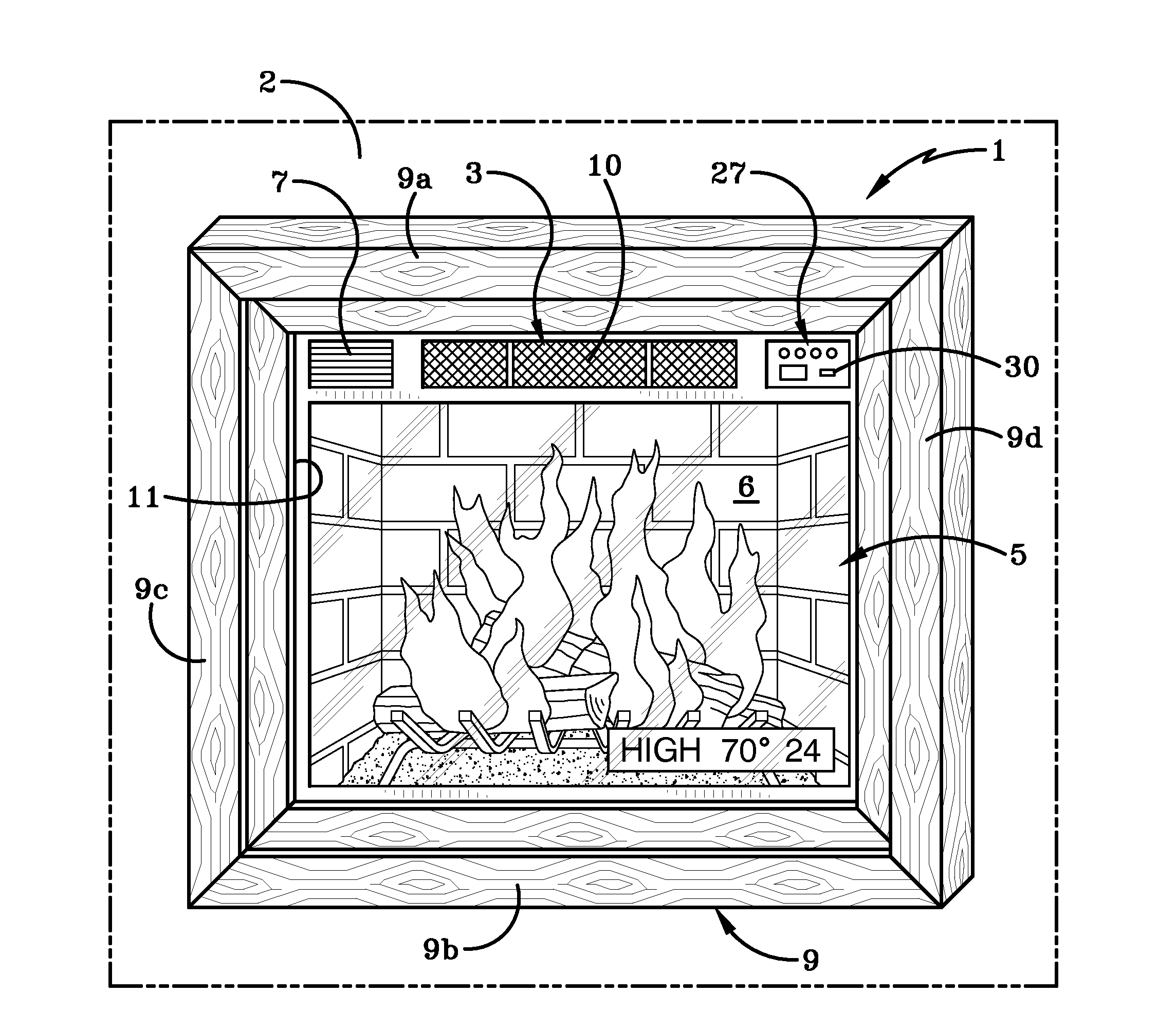
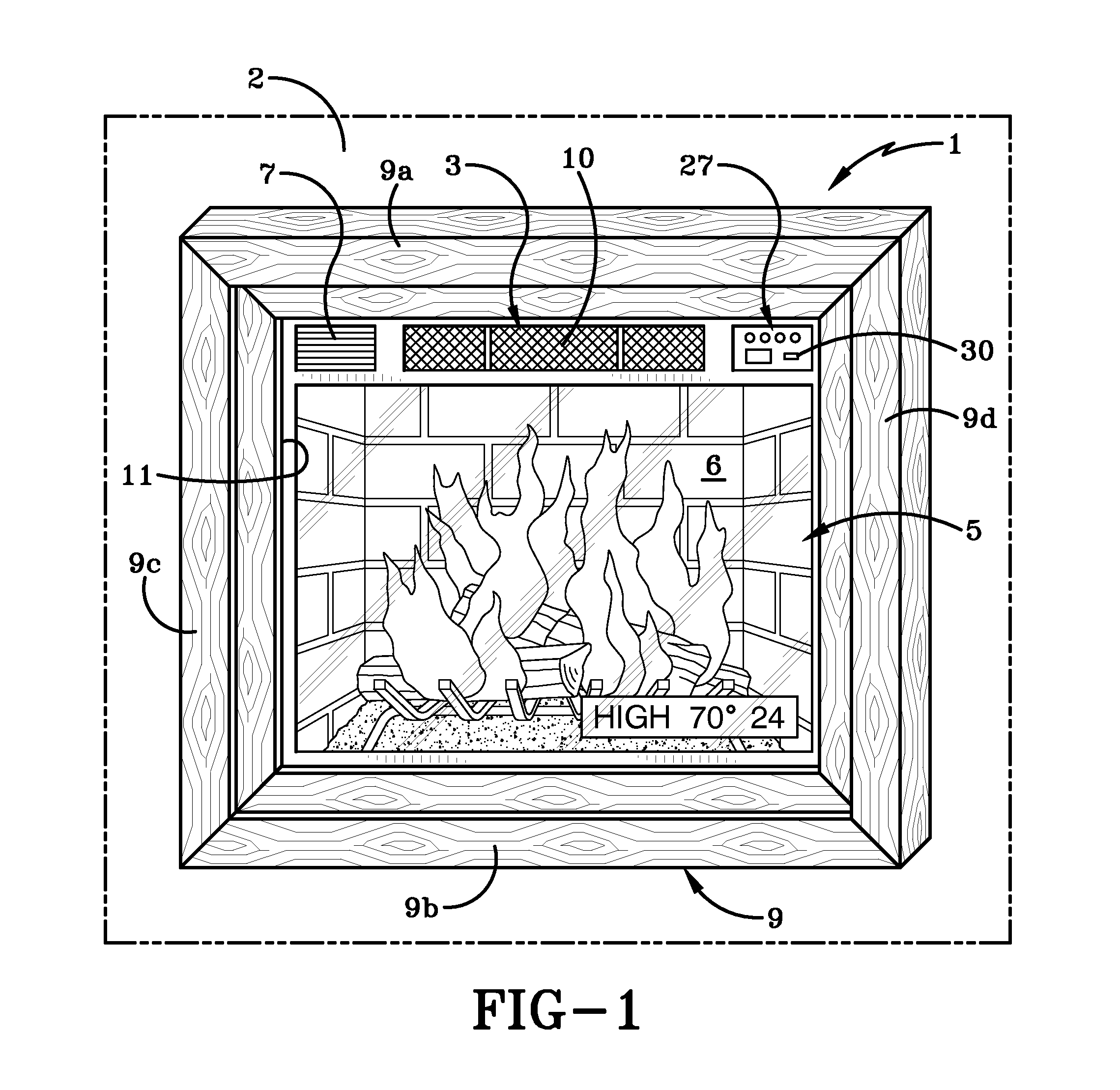
[0021]FIG. 1 illustrates a first preferred embodiment of a decorative television / space heater combination device, generally indicated at 1. Device 1 is shown mounted on a vertical wall 2. Device 1 comprises a space heater 3 and a television 5 which are engaged with each other and mounted in a decorative frame 9. Space heater 3, television 5 and frame 9 are all pre-assembled into the television / space heater combination device 1 illustrated in FIG. 1 and little to no assembly is required after purchase. The purchaser will simply mount frame 9 including the television / space heater onto wall 2 and device 1 is then ready for operation. It will be understood that television 5 and space heater 3 may be fabricated as separate components and then secured together by any suitable means such as by way of fastener brackets. Alternatively, television 5 and space heater 3 may be fabricated into a single or integral device and then mounted within frame 9.

[0022]Space heater 3 preferably is an elect...


PUM


Abstract

A television/space heater combination device for displaying image content and for heating air and method of using the same is presented. The television/space heater combination device includes a television, a space heater and, sometimes, a frame. The method of use includes activating the space heater; selecting a temperature value for the space heater; generating heat and distributing the same into a room from the space heater; activating the television; and displaying an image on a screen of the television while generating heat with the space heater. The displayed image may be an image of a wood or gas burning fireplace generated by a continuous video loop; or be images from regular television programming or images generated by data transmitted to the television by a remote computer.

Description

CROSS-REFERENCE TO RELATED APPLICATIONS[0001]This application claims the benefit of U.S. Provisional Patent Application Ser. No. 61 / 607,738 filed, Mar. 7, 2012, the entire specification of which is incorporated herein by reference.BACKGROUND OF THE INVENTION[0002]1. Technical Field[0003]The current invention relates generally to apparatus, systems and methods for heating air. More particularly, the apparatus, systems and methods relate to heating air with a space heater. Specifically, the apparatus, systems and methods provide for heating a space with a space heater that is engaged with a television, and where the space heater is operable separately and in combination with the television.[0004]2. Background Information[0005]Space heaters are used to heat areas of a building or a home without requiring the central heating system to heat the entire home or building. The use of space heaters may reduce the overall heating cost for the building because one room or a couple of rooms may ...

Claims


Application Information

Patent Timeline
Patent Type & Authority Applications(United States)
IPC IPC(8): H05B1/00
CPCH05B1/00H04N21/4131H04N21/414H04N21/42212H04N5/64F24H3/0411
Inventor GALLO, CHRISTOPHER J.
Owner SEBOLT JOSEPH A
Why Eureka
Try Eureka