Optical transceiver having improved functions to load control program

Active Publication Date: 2013-09-12
SUMITOMO ELECTRIC IND LTD
View PDF3 Cites 9 Cited by
  • Summary
  • Abstract
  • Description
  • Claims
  • Application Information

AI Technical Summary

Problems solved by technology

However, the SFP transceiver and / or the XFP transceivers have no extra terminals especial to download the program.

Method used


Image

  • Optical transceiver having improved functions to load control program
  • Optical transceiver having improved functions to load control program
  • Optical transceiver having improved functions to load control program

Examples


second embodiment

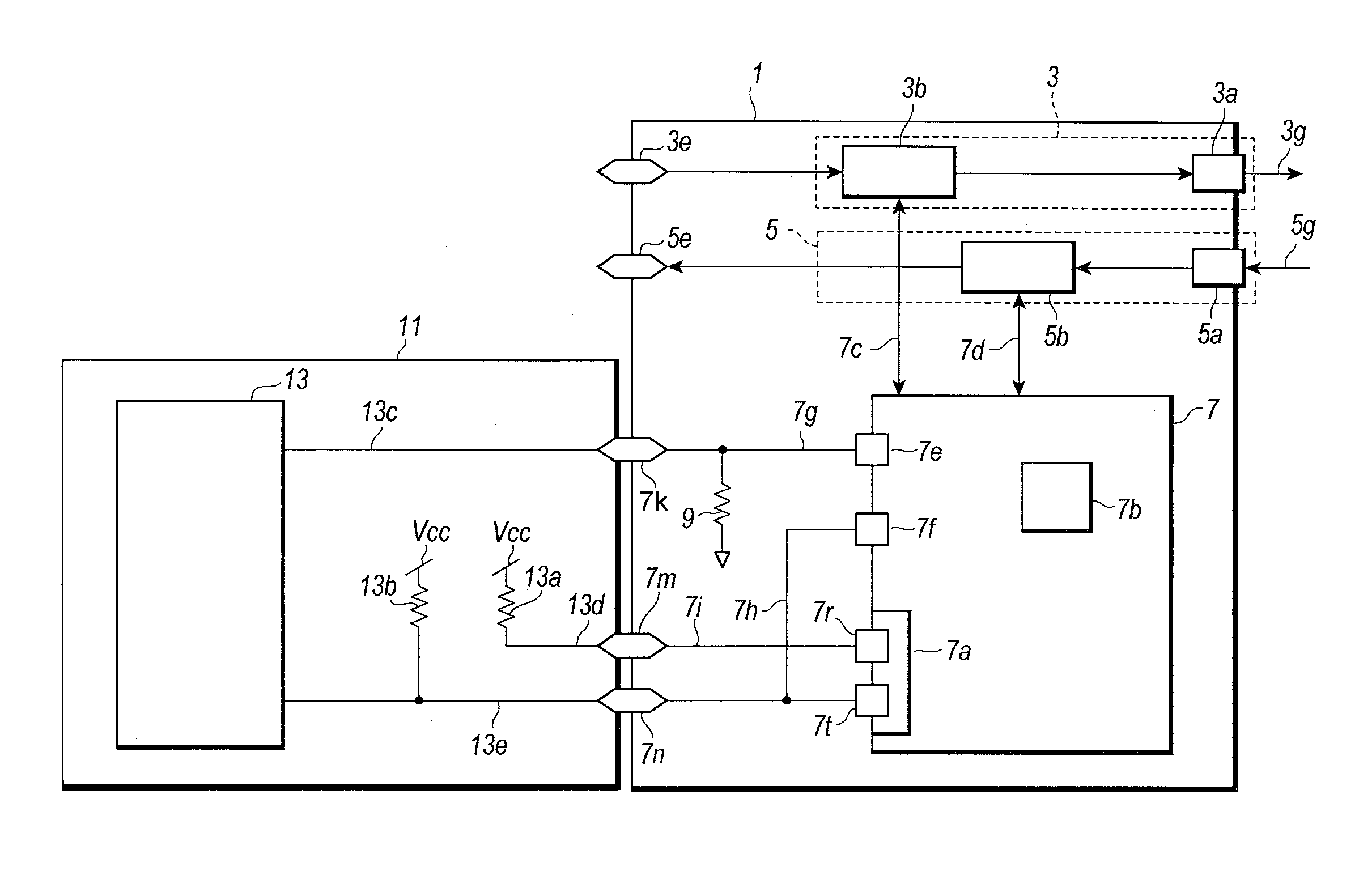
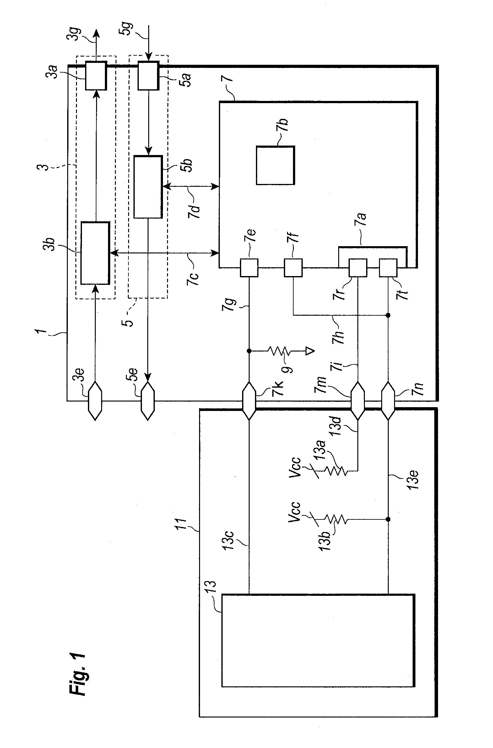
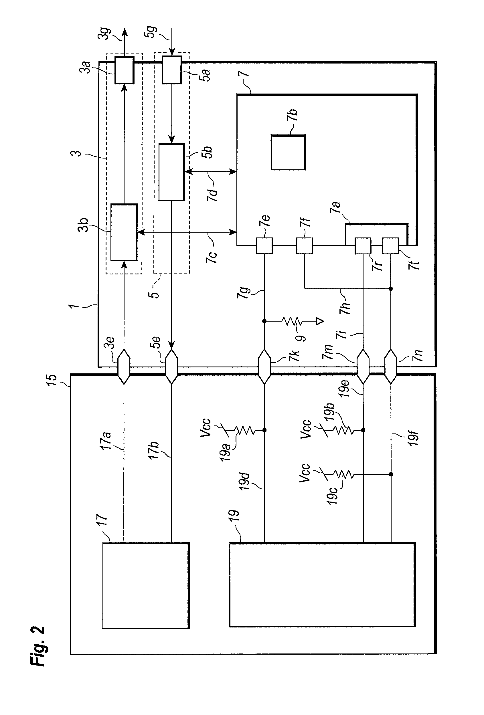
[0051]FIG. 7 is a functional block diagram of an XFP transceiver 1B and a loader 11B; while, FIG. 8 is a functional block diagram of the XFP transceiver 1B set in the host system 15. The XFP transceiver 1B also includes an optical transmitter 3, an optical receiver 5, and a controller 7B. The optical transmitter 3 and the optical receiver 5 have arrangements substantially same to those in the aforementioned SFP transceiver 1. However, the controller 7B of the XFP transceiver 1B and circuits around the controller 7B, in particular, the circuits for communicating with the host system 15 are different from those in the SFP transceiver 1.

[0052]The XFP transceiver 1B includes, as external terminals, P_Down 7p, Mod_Abs 7q, Mod_DeSel 7r, SCL 7m, and SDA 7n. The Mod_Abs terminal 7k has similar function with MOD_DEF0 in the SFP transceiver 1, that is, Mod_Abs terminal 7n is pulled down to the ground through a resistor 9c in the XFP transceiver 1B. The host system may detect whether it receiv...


PUM


Abstract

Methods to load control programs into an optical transceiver whose specifications follow the standards are disclosed. The standard transceiver, such as SFP transceiver and / or XFP transceiver, provides control terminals in addition to the serial interface to communicate with the host device. The control terminals are inactive when the transceiver is output of the host device. The loader to load the program utilizes those control terminals and the optical transceiver of the invention provides mechanisms to use those control terminals for downloading the program.

Description

BACKGROUND OF THE INVENTION[0001]1. Field of the Invention[0002]The present application relates to an optical transceiver, in particular, the application relates to an optical transceiver whose architecture follows standards defined by multi sources.[0003]2. Background Arts Optical transceivers, in particular, pluggable optical transceivers generally follow multi-source agreements (hereafter denoted as “MSA”) for electronic and mechanical specifications thereof. For instance, one of the MSAs regarding to, what is called, the small form factor pluggable (SFP) defines several control signals called as MOD_DEF0, MOD_DEF1 and MOD_DEF2. Another MSA called as the XFP (10 Gbit Small Form Factor Pluggable) also defines control signals, or control pins of Mod_Abs, Mod_DeSel, P_Down, and Tx_DIS.[0004]In another aspect, the optical transceivers are necessary to be revised in a control program thereof. The optical transceivers generally provide a controller to execute a program stored in the co...

Claims


Application Information

Patent Timeline
Patent Type & Authority Applications(United States)
IPC IPC(8): H04B10/40
CPCH04B10/40
Inventor TANAKA, YASUHIROISHIBASHI, HIROTO
Owner SUMITOMO ELECTRIC IND LTD
Why Eureka
Try Eureka