
Groove insert, clamping holder for a groove insert and groove cutting tool

Active Publication Date: 2013-09-12
KENNAMETAL INC
View PDF21 Cites 31 Cited by
  • Summary
  • Abstract
  • Description
  • Claims
  • Application Information

AI Technical Summary

Benefits of technology

The invention aims to improve the anchoring and positioning of a groove insert in a receiving means. It introduces a clamping holder and a groove cutting tool that allow for precise mounting even in the case of a lateral feed. Overall, the invention enhances the stability and reliability of the groove insert during use.

Problems solved by technology

This can cause problems precisely where there is a lateral feed.

Method used


Image

  • Groove insert, clamping holder for a groove insert and groove cutting tool
  • Groove insert, clamping holder for a groove insert and groove cutting tool
  • Groove insert, clamping holder for a groove insert and groove cutting tool

Examples


Embodiment Construction

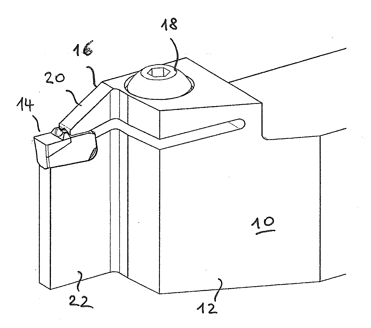
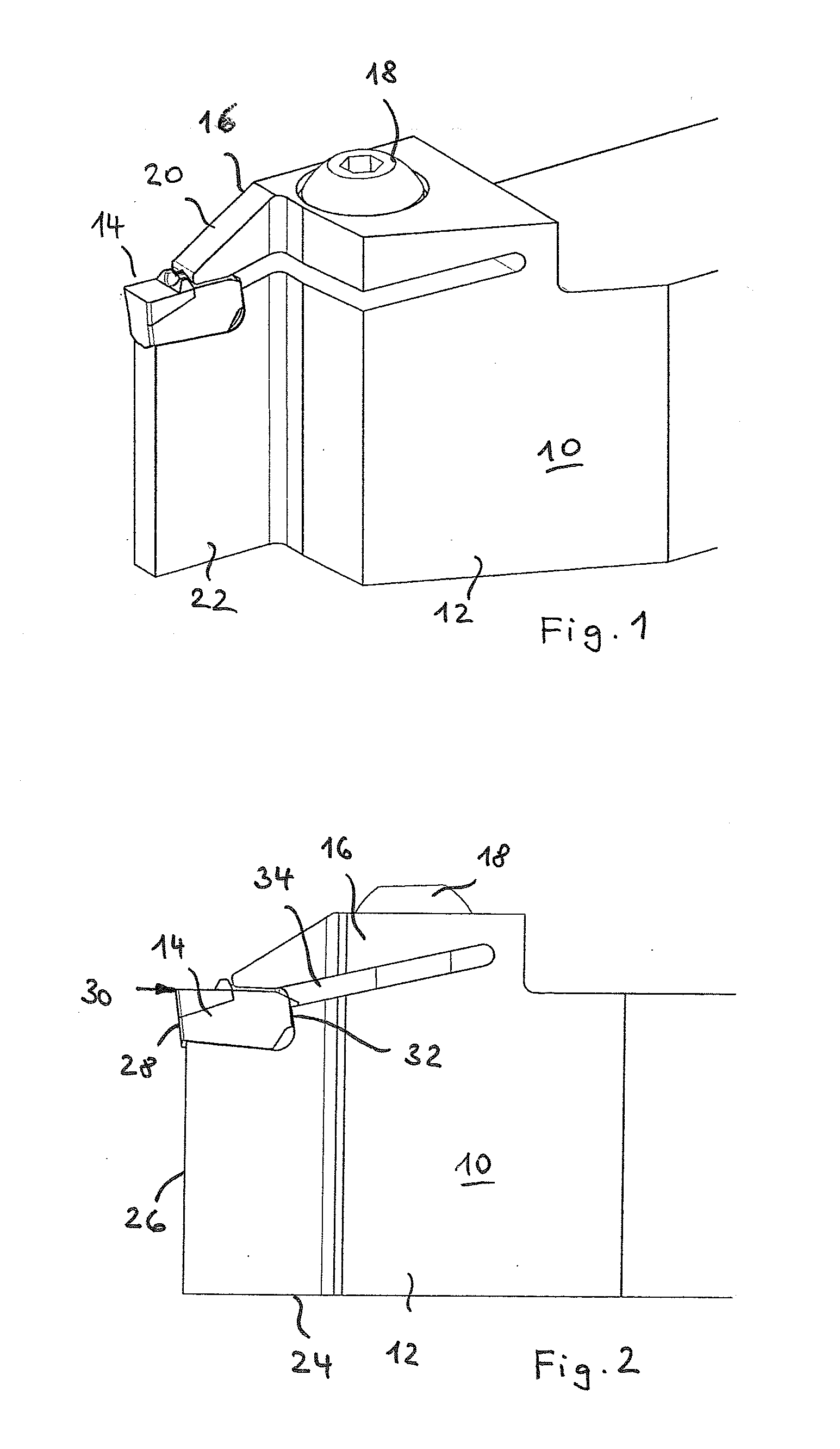
[0052]FIG. 1 shows a groove cutting tool, for example for cutting grooves. The groove cutting tool includes a clamping holder 10, which has a carrier 12 for a groove insert 14 and a clamping jaw 16 which is integrally molded on the carrier 12. The clamping jaw 16 has on its top side a through-opening, through which a clamping means 18 in the form of a clamping screw extends as far as into the carrier 12, where a thread is realized (see FIG. 7).

[0053]The clamping jaw 16 presses from above onto the insert 14 and clamps said insert between itself and the carrier 12.

[0054]It can be seen in FIG. 1 that the width of the groove insert 14 is the same as or ever greater than the width of a narrow arm 20 of the clamping jaw 16 and greater than the width of a narrow web 22 of the carrier 12, both of which come directly into contact with the groove insert 14. The tool is able to cut deeply into a workpiece by means of the narrow embodiment of the arm 20, the web 22 and the groove insert 14.

[005...


PUM

PropertyMeasurementUnit
Angleaaaaaaaaaa
Angleaaaaaaaaaa
Angleaaaaaaaaaa

Abstract

A groove insert to be received in a tool holder has, along its top and bottom side and on its rear side, a holding structure which is formed by holding faces which taper toward one another and by way of which the groove insert is fixed in the tool holder in a positive locking manner. The tool holder has corresponding counter faces. The groove insert and the tool holder form a groove cutting tool.

Description

FIELD OF THE INVENTION[0001]The invention relates to a groove insert to be received in a clamping holder, said groove insert having two opposite ends, wherein the insert has on one end a front side which forms the main free face and on the opposite end a rear side which extends substantially parallel to the front side, and having a top and a bottom side as well as side faces, wherein a major edge is formed between the front side and the top side.[0002]Over and above this, the invention relates to a clamping holder having a receiving means for a groove insert as well as to a groove cutting tool having a clamping holder and a groove insert, which is detachably fastened thereon.BACKGROUND OF THE INVENTION[0003]Groove inserts are installed in lathe tools or also in milling cutters as a replaceable unit in order to be replaced in the event of wear. Groove inserts are extremely narrow items to be installed such that their secure fastening in the clamping holder has to be ensured. This can...

Claims


Application Information

Patent Timeline
IPC IPC(8): B23B27/16B23B29/04
CPCB23B27/04B23B2205/02B23B27/1611Y10T407/28Y10T407/24Y10T407/2282B23B29/043
Inventor KAUFMANN, IGORABDUL, ANWAR SADAT MOHIDEENHAVRDA, FRANZ
Owner KENNAMETAL INC
Features
  • Generate Ideas
  • Intellectual Property
  • Life Sciences
  • Materials
  • Tech Scout
  • Unparalleled Data Quality
  • Higher Quality Content
  • 60% Fewer Hallucinations
Learn More