Interchangeable valve for a valve block used with a glass machine

a technology of glass machines and interchangeable valves, which is applied in the direction of multiple way valves, lift valves, valve details, etc., can solve the problem of difficult access to the mounting screws of the bottom valves

Active Publication Date: 2013-09-19
ROSS EUROPA
View PDF4 Cites 4 Cited by
  • Summary
  • Abstract
  • Description
  • Claims
  • Application Information

AI Technical Summary

Problems solved by technology

It is difficult to access the mounting screws of the bottom valves when the bottom valves need to be changed, repaired or for maintenance due to the location of the mounting screws.

Method used


Image

  • Interchangeable valve for a valve block used with a glass machine
  • Interchangeable valve for a valve block used with a glass machine
  • Interchangeable valve for a valve block used with a glass machine

Examples


Embodiment Construction

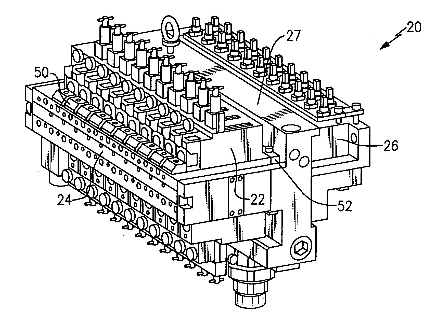
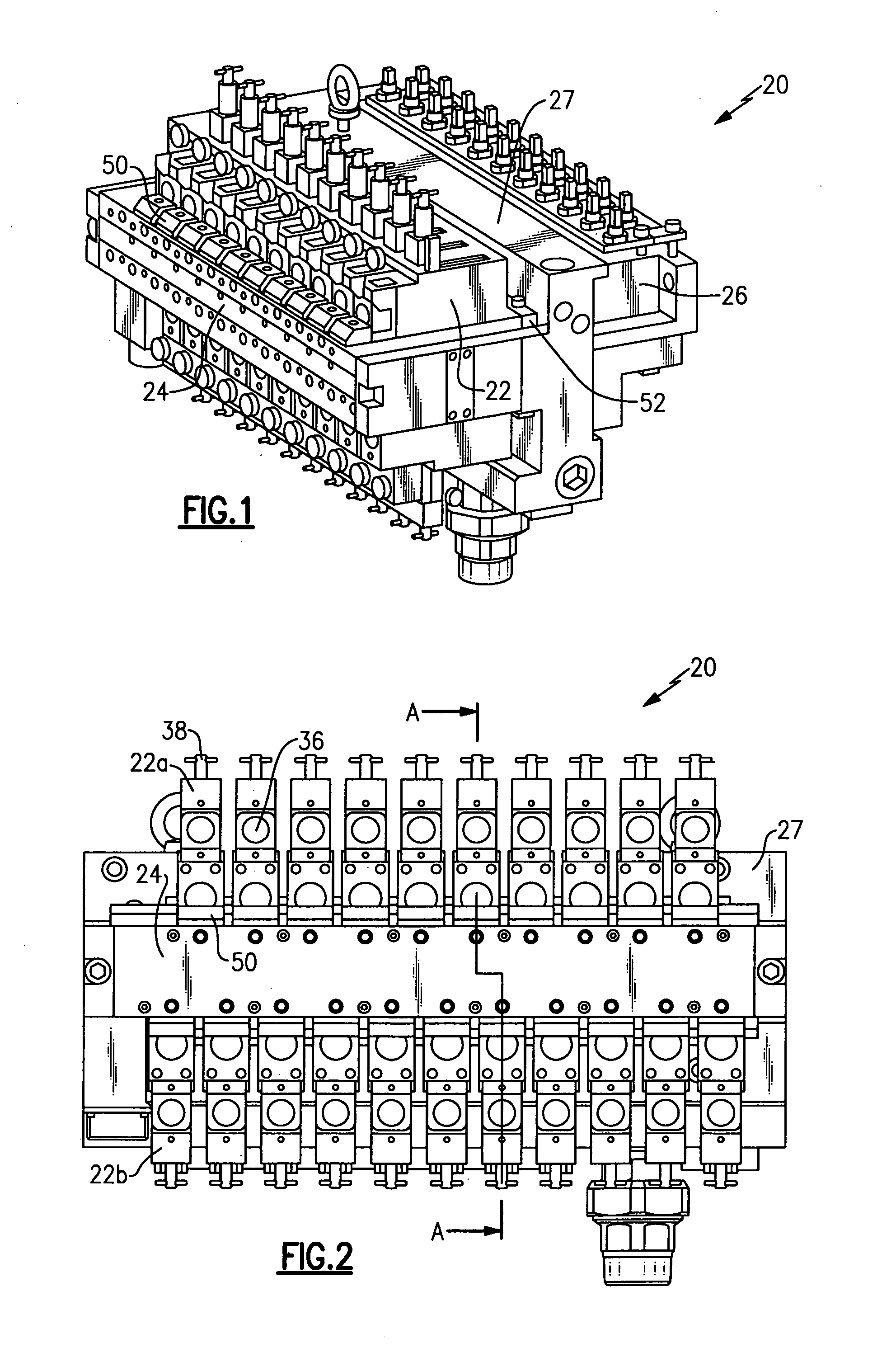
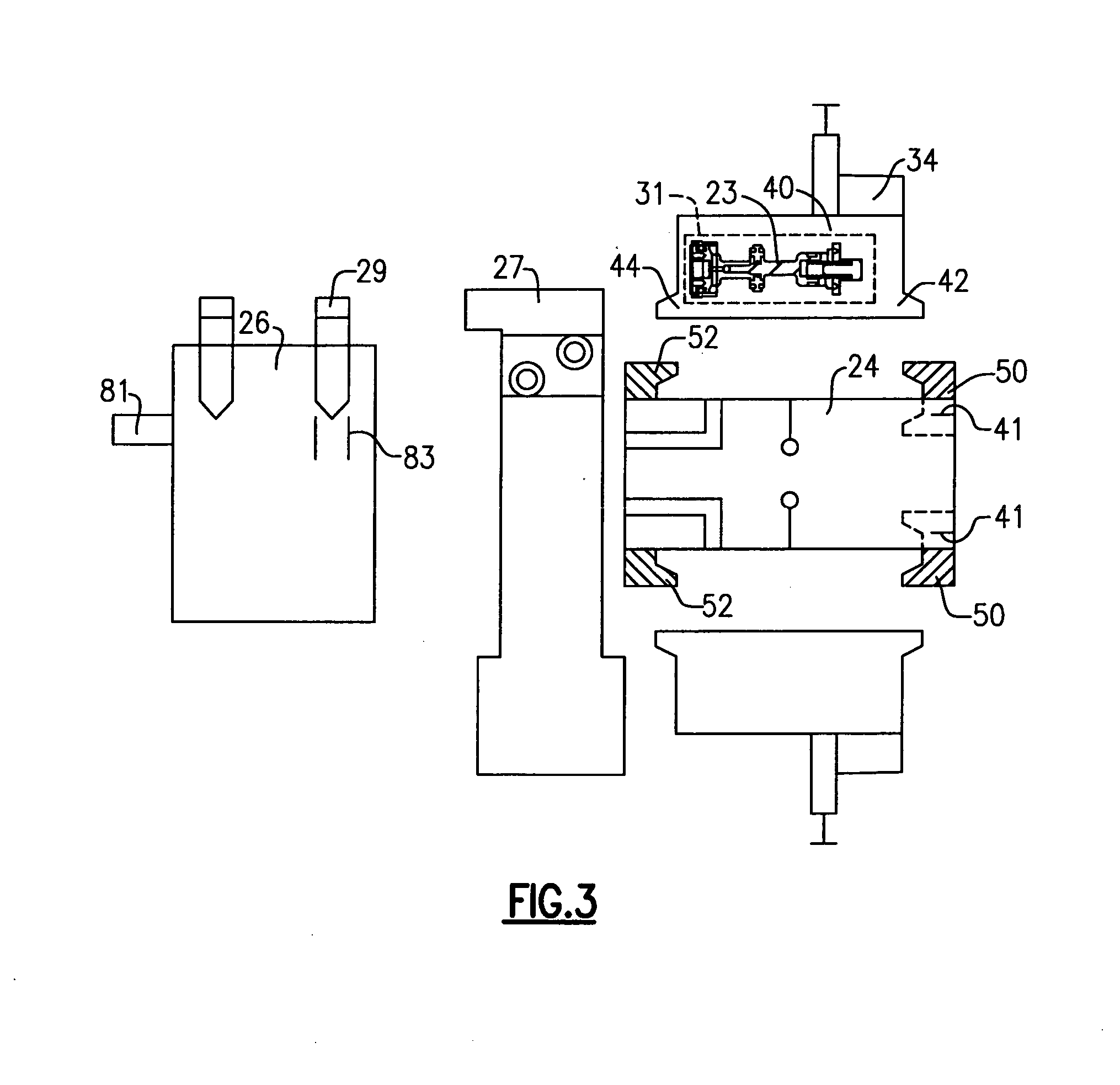
[0018]FIGS. 1, 2 and 3 illustrate a valve block with single touch interchangeable valves 20 used to control functions in a process of forming hollow glass bottles 78. Usually, the valve block with single touch interchangeable valves 20 includes twenty one (21) valves 22. However, the valve block with single touch interchangeable valves 20 could include twenty six (26) valves 22. The valve block with single touch interchangeable valves 20 includes a base 24 to which the valves 22 are mounted. Eleven valves 22 are located on a top row of the base 24, and ten valves 22 are located on a bottom row of the base 24.

[0019]An air entry unit 27 supplies the base 24 with pressurized air, and a speed control unit 26 is also mounted to the air entry unit 27. The speed control unit 26 controls parameters, such as the air speed and the amount of air flowing into the glass making machine by the use of a needle valve 83. By moving a needle 29 downwardly, the airflow through a port 81 to the glass ma...


PUM


Abstract

An air valve manifold (20) to be used with a glass making machine includes a base (24) and a valve (22) including a valve body attached to the base (24). The valve body includes a first projection (42) on a front of the valve body and an opposing second projection (44) on an opposing rear of the valve body. A first attachment feature (50) is secured to the front of the base to retain at least a portion of the first projection (42) of the valve body. A second attachment feature (52) is secured to the base to retain at least a portion of the opposing second projection (44) of the valve body.

Description

BACKGROUND OF THE INVENTION[0001]The present invention relates generally to a single touch interchangeable valve used in a valve block used with a glass making machine.[0002]In prior systems, a top group of valves are located on a top surface of a valve block base, and a bottom group of valves are located on a bottom surface of the valve block base. Each of the top valves are attached to the valve block base by mounting screws that are inserted in a vertical direction from the top, and each of the bottom valves are attached to the valve block base by mounting screws that are inserted in a vertical direction from the bottom. In one prior system, four mounting screws are employed to secure each valve to the valve block base. It is difficult to access the mounting screws of the bottom valves when the bottom valves need to be changed, repaired or for maintenance due to the location of the mounting screws.SUMMARY OF THE INVENTION[0003]An air valve manifold includes a base and a valve inc...

Claims


Application Information

Patent Timeline
Patent Type & Authority Applications(United States)
IPC IPC(8): F16K27/00F16K11/20
CPCC03B9/3636C03B9/406F16K27/00F16K11/20F16K27/003Y10T137/87885
Inventor HARTWIG, JOHANNES
Owner ROSS EUROPA
Why Eureka
Try Eureka