Echo canceler and echo detector

a detector and echo technology, applied in the field of techniques, can solve the problems of reducing the estimation accuracy of echo signal power, avoiding conventional methods, and carrying out right observation, and achieve the effect of suppressing residual echo and facilitating telephone conversation

Inactive Publication Date: 2013-09-26
MITSUBISHI ELECTRIC CORP
View PDF2 Cites 24 Cited by
  • Summary
  • Abstract
  • Description
  • Claims
  • Application Information

AI Technical Summary

Benefits of technology

[0010]According to the present invention, it can provide a suitable telephone conversation environment by suppressing the residual echo without hindering the telephone conversation due to the excessive suppression of the send voice even when telephone conversation is carried out in the condition where large noise occurs or the echo path changes.

Problems solved by technology

However, the foregoing conventional method that determines the echo suppression quantity from the power of the estimated echo signal calculated from the amount of acoustic coupling has two problems.
First, when background noise is large, since an echo gets buried in the background noise, it cannot carry out right observation of the amount of acoustic coupling, which offers a problem of reducing the estimation accuracy of the echo signal power.
Second, when the amount of acoustic coupling itself varies because of a change of an echo path, it becomes necessary to reobserve the amount of acoustic coupling, which offers a problem of being unable to suppress the echo appropriately until an appropriate echo suppression quantity can be obtained by calculating an accurate observed value.
As a result, under the foregoing condition, the echo suppression quantity is not calculated correctly, which offers a problem of causing a residual echo or hindering telephone conversation because of excessive suppression of the send voice.
Thus, the foregoing conventional technique has the problems of bringing about the residual echo because of being unable to compute the appropriate echo suppression quantity or hindering the telephone conversation because of the excessive suppression of the send voice when carrying out the telephone conversation under the large noise or in an environment where the echo path varies.

Method used


Image

  • Echo canceler and echo detector
  • Echo canceler and echo detector
  • Echo canceler and echo detector

Examples


embodiment 1

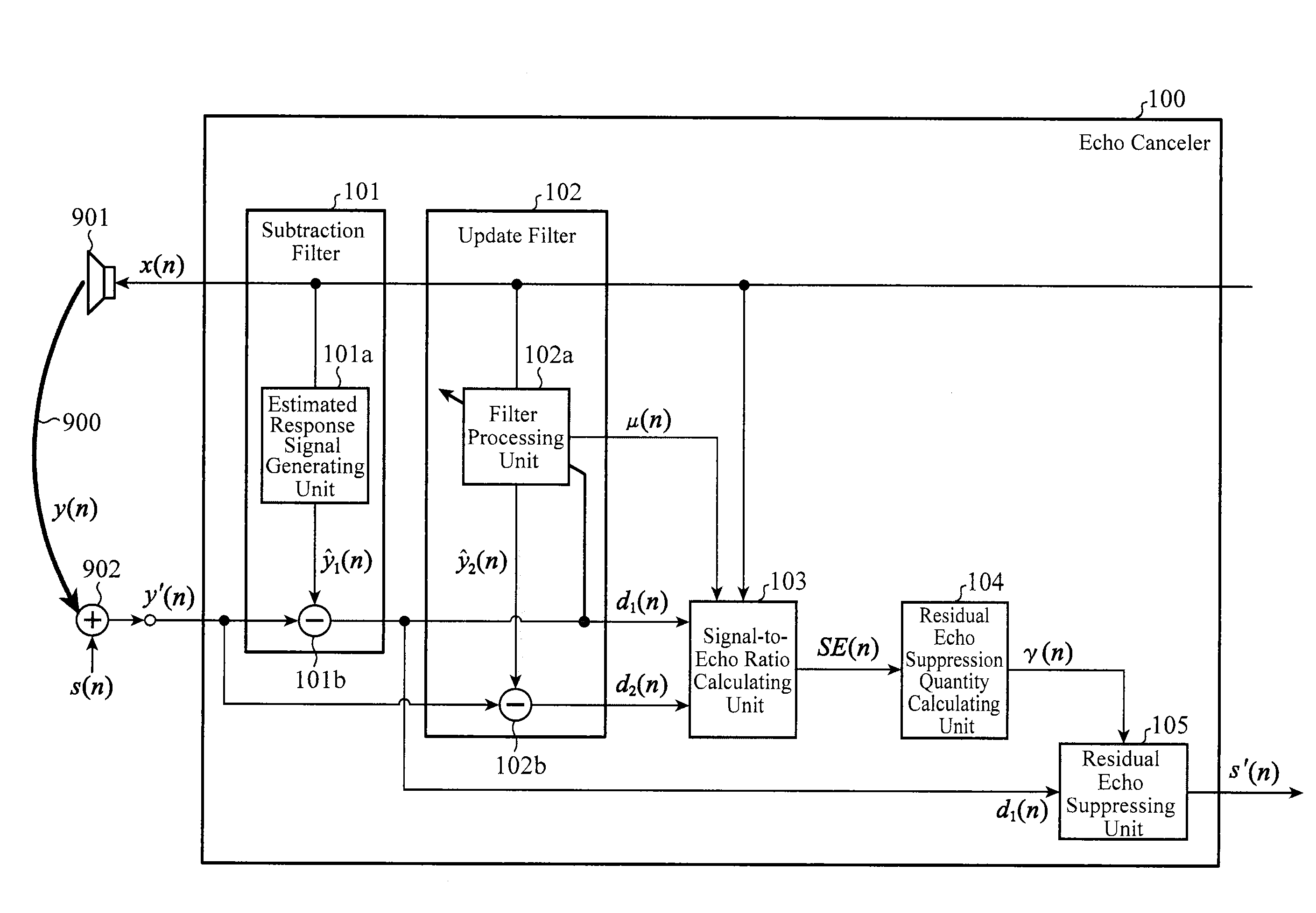
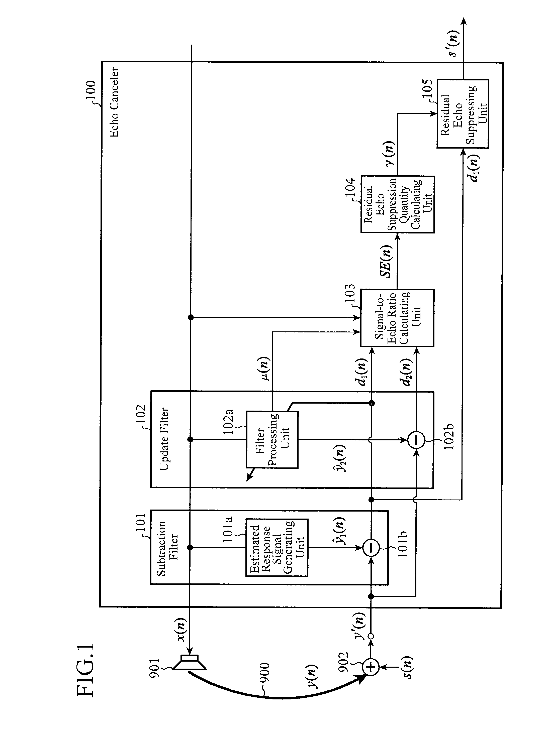
[0018]FIG. 1 is a block diagram showing a configuration of an echo canceler of an embodiment 1. In FIG. 1, the echo canceler 100 comprises a subtraction filter 101 for generating a first estimated echo signal and a first residual signal; an update filter 102 for carrying out a coefficient update of a filter coefficient sequence and for generating a second estimated echo signal and a second residual signal using the updated filter coefficient sequence; a signal-to-echo ratio calculating unit 103 for computing a signal-to-echo ratio; a residual echo suppression quantity calculating unit 104 for calculating the suppression quantity of a residual echo; and a residual echo suppressing unit 105 for suppressing the residual echo. Furthermore, the subtraction filter 101 comprises an estimated response signal generating unit 101a and a subtractor 101b, and the update filter 102 comprises a filter processing unit 102a and a subtractor 102b.

[0019]In addition, as shown in FIG. 1, the echo canc...

embodiment 2

[0073]An echo detector comprising the subtraction filter 101, update filter 102 and signal-to-echo ratio calculating unit 103 shown in the foregoing embodiment 1 will be described. FIG. 3 is a block diagram showing a configuration of an echo detector of an embodiment 2.

[0074]In FIG. 3, the echo detector 200 comprises an echo detecting unit 201 instead of the residual echo suppression quantity calculating unit 104 and the residual echo suppressing unit 105 of the echo canceler 100 shown in the embodiment 1. Incidentally, in FIG. 3, the same components as those of the echo canceler 100 shown in FIG. 1 of the embodiment 1 are designated by the same reference numerals and their description will be omitted.

[0075]The signal-to-echo ratio calculating unit 103 calculates, according to the foregoing Expression (18), the signal-to-echo ratio SE(n) using the received signal x(n), the first residual signal d1(n) obtained by the subtraction filter 101, the second residual signal d2(n) obtained b...

embodiment 3

[0080]The foregoing embodiment 1 shows a configuration which causes the update filter 102 to update the updated filter coefficient sequence using the received signal x(n) and the microphone input signal y′(n), and to obtain the second residual signal d2(n) soon after that using the same received signal x(n) and microphone input signal y′(n), and which uses them for computing the signal-to-echo ratio SE(n).

[0081]However, although the received signal x(n) and the near-end signal s(n) are uncorrelated in general, correlation sometimes appear between the received signal x(n) and the near-end signal s(n) and hence there are some cases where the update filter coefficient ĥ(n+1) outputs the second estimated echo signal ŷ2(n) that will eliminate part of the near-end signal s(n) in the microphone input signal y′(n) supplied. In this case, there are some cases where the variance σd22(n) of the second residual signal d2(n) is reduced temporarily, which can sometimes hinder accurate calculation...


PUM


Abstract

An echo canceler includes a signal-to-echo ratio calculating unit 103 and a residual echo suppressing unit 105. The signal-to-echo ratio calculating unit 103 computes a signal-to-echo ratio SE(n) indicating a ratio of an echo component to a received signal x(n) from a first residual signal and a second residual signal. The first residual signal is obtained using a filter coefficient sequence of an update filter 102, which is obtained up to the previous operation. The second residual signal is obtained using an updated filter coefficient sequence that undergoes a coefficient update which is performed, using an arbitrary update step size μ(n), on the filter coefficient sequence of the update filter 102, which is obtained up to the previous operation. The residual echo suppressing unit 105 suppresses the echo component contained in the microphone input signal in accordance with the signal-to-echo ratio the signal-to-echo ratio calculating unit 103 computes.

Description

TECHNICAL FIELD[0001]The present invention relates to a technique for detecting an echo of a received signal mixed into a send signal and for canceling the detected echo from the send signal.BACKGROUND ART[0002]An echo canceler is generally configured as a combination of a linear echo processing unit for canceling a linear echo component and a residual echo suppression processing unit for suppressing the linear echo component that cannot be canceled out by the linear echo processing and a nonlinear echo component. Such a configuration is disclosed in Non-Patent Document 1, for example. The echo canceler disclosed in the Non-Patent Document 1, however, has a problem in that when an echo and send voice overlap each other, that is, when double talk occurs, the residual echo suppression processing unit suppresses both the residual echo and send voice.[0003]To solve the foregoing problem, Patent Document 1, for example, discloses a method of flexibly controlling suppression coefficients ...

Claims


Application Information

Patent Timeline
Patent Type & Authority Applications(United States)
IPC IPC(8): G10K11/16
CPCH04M9/082H04R3/02G10K11/16
Inventor AWANO, TOMOHARUYANO, ATSUYOSHIMATSUOKA, BUNKEI
Owner MITSUBISHI ELECTRIC CORP
Why Eureka
Try Eureka