Playing apparatus, method, and program recording medium

a technology of playing apparatus and recording medium, applied in the field of playing apparatus, a playing method, and a program recording medium, can solve the problems of playing apparatus, generating a musical tone of a different tone color, and delay in sound generation

Active Publication Date: 2013-10-03
CASIO COMPUTER CO LTD
View PDF26 Cites 24 Cited by
  • Summary
  • Abstract
  • Description
  • Claims
  • Application Information

AI Technical Summary

Benefits of technology

[0012]The playing apparatus according to the invention can generate a musical tone of a tone color corresponding to the stick position at the correct shot timing, even if the sick has been swung slantwise.

Problems solved by technology

In the playing apparatus, a time delay from the time when a timing signal of sound generation is produced to the time when a musical tone is generated is not considered, and therefore a problem is invited that can delay the timing of sound generation.
But the playing apparatus has a disadvantage that can generate a musical tone of a tone color different from a musical tone of a tone color supposed to be generated, in accordance with the position of the stick at the correct shot timing, when the stick is swung down slantwise.

Method used


Image

  • Playing apparatus, method, and program recording medium
  • Playing apparatus, method, and program recording medium
  • Playing apparatus, method, and program recording medium

Examples


first embodiment

[Sound-Generation Timing Detecting Process (First Embodiment)]

[0105]FIG. 12 is a flow chart showing the process of detecting a timing of sound generation performed in the first embodiment of the invention.

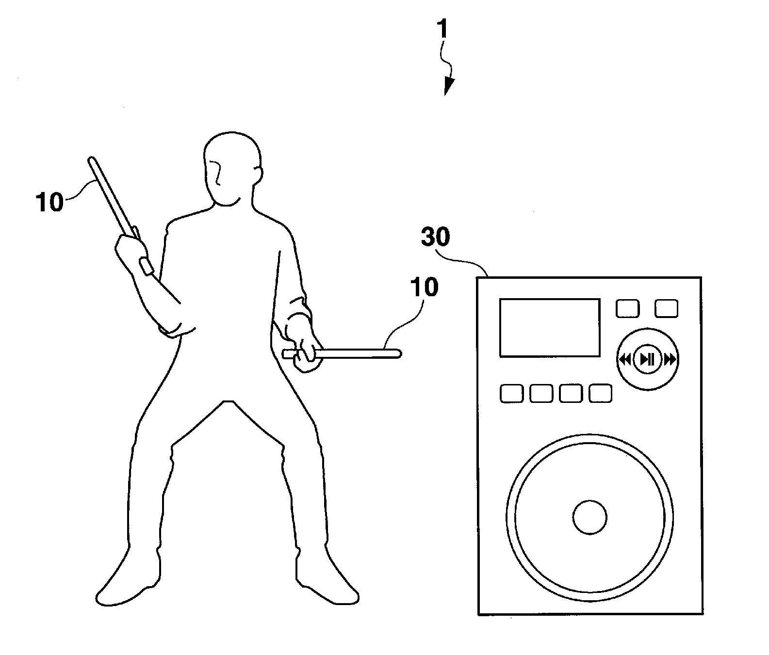
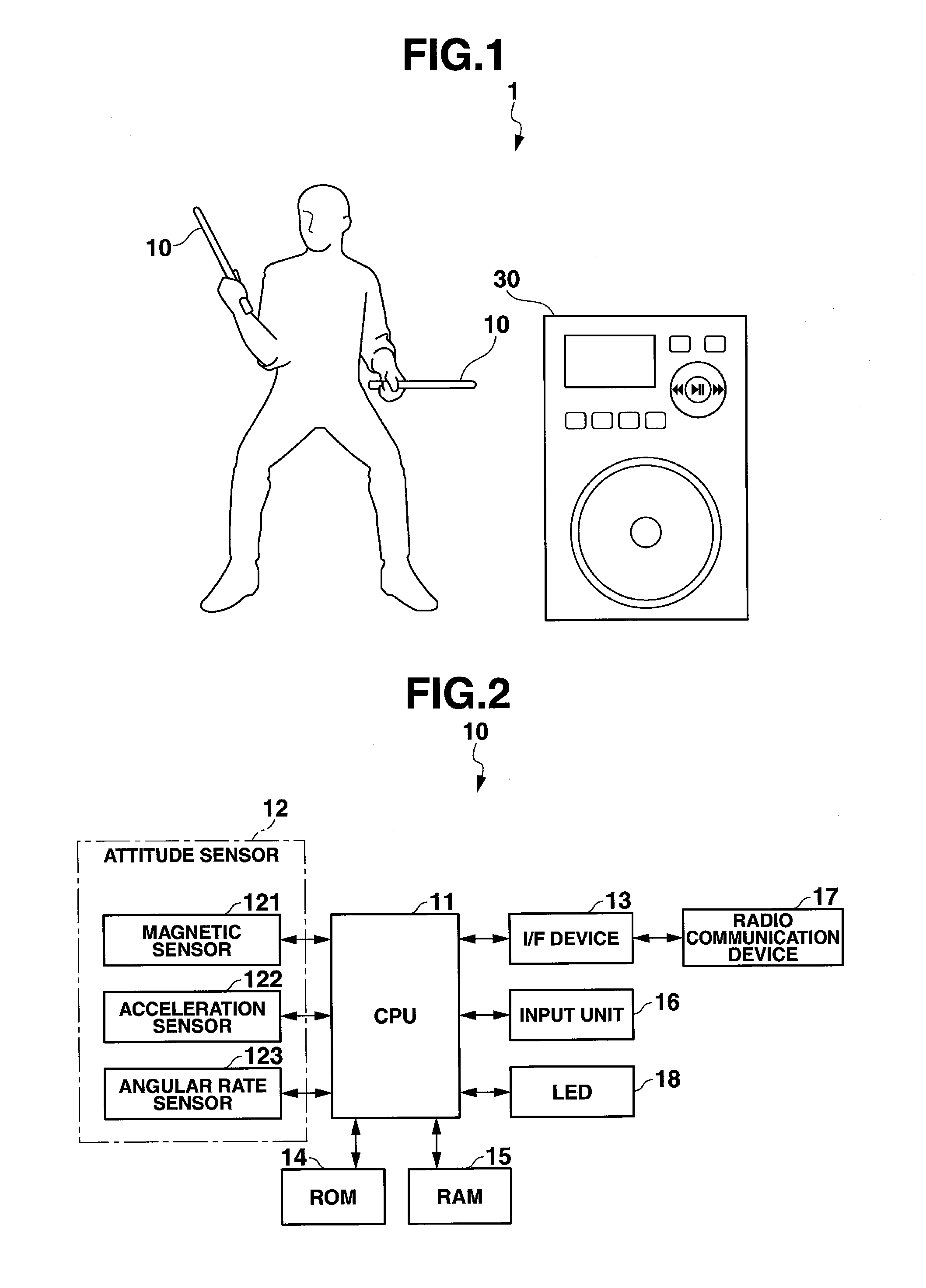
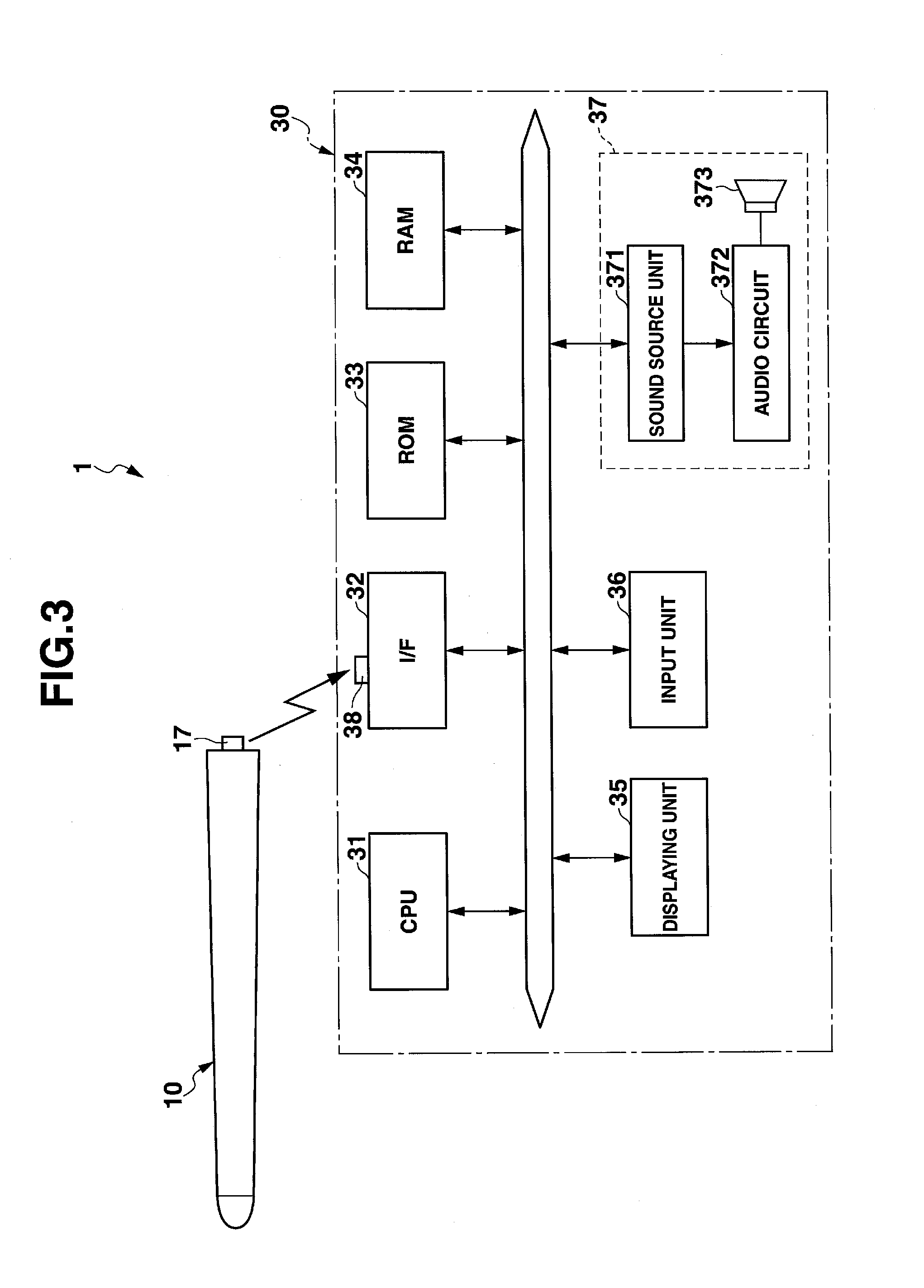
[0106]CPU 11 judges in which operating state the stick unit 10 has been held (step S302). Four operating states such as IDLE, ACTION, SHOT, and DONE are prepared for the stick unit 10. When the stick unit 10 is held in the operation state of IDLE, CPU 11 advances to step S303. When the stick unit 10 is held in the operation state of ACTION, CPU 11 advances to step S320. When the stick unit 10 is held in the operation state of SHOT, CPU 11 advances to step S330. When the stick unit 10 is held in the operation state of DONE, CPU 11 advances to step S340.

[0107]A typical transition of the operating state of the stick unit 10 is shown in FIG. 14C. In FIGS. 14A, 14B, 14C and 14D, the abscissa axis is a temporal axis, that is, a time is plotted along the abscissa axis. In FIG. 14A, the an...

second embodiment

[Sound-Generation Timing Detecting Process (Second Embodiment)]

[0117]FIG. 13 is a flow chart of the process of detecting a timing of sound generation performed in the second embodiment of the invention. CPU 11 judges in which operating state the stick unit 10 has been held (step S352). Four operating states such as IDLE, ACTION, SHOT, and DONE are prepared for the stick unit 10. When the stick unit 10 is held in the operation state of IDLE, CPU 11 advances to step S353. When the stick unit 10 is held in the operation state of ACTION, CPU 11 advances to step S370. When the stick unit 10 is held in the operation state of SHOT, CPU 11 advances to step S380. When the stick unit 10 is held in the operation state of DONE, CPU 11 advances to step S390. The typical transition of the operating state of the stick unit 10 is the same as in the first embodiment, as shown in FIG. 14C.

[0118]When the angular acceleration of the stick unit 10 is not positive (NO at step S353), CPU 11 finishes the p...


PUM


Abstract

A sensor obtains an angular rate of a stick member. A sound source map includes plural areas disposed in a virtual space. CPU presumes a direction of a turning axis of the stick member based on the angular rate obtained by the sensor, while a user is operating the stick member, calculates an angular rate of a top of the stick member based on the angular rate obtained by the sensor with the angular rate in the longitudinal direction of the stick member removed, calculates a position of the holding member in the virtual space after a predetermined time, based on the recent direction of the turning axis of the stick member and recent angular rate of the top of the stick member, and sends a sound generating unit a note-on event of a musical tone assigned to an area corresponding to the calculated position among the plural areas.

Description

CROSS-REFERENCE TO RELATED APPLICATION[0001]The present application is based upon and claims the benefit of priority from the prior Japanese Patent Application No. 2012-084371, filed Apr. 2, 2012, the entire contents of which are incorporated herein by reference.BACKGROUND OF THE INVENTION[0002]1. Field of the Invention[0003]The present invention relates to a playing apparatus, a playing method, and a program recording medium.[0004]2. Description of the Related Art[0005]In the past, a playing apparatus was proposed, which generated a sound corresponding to a player's motion, when sensing the player's playing motion. For example, a playing apparatus is known, which consists only of a stick member and generates percussion sounds. The stick member of this conventional playing apparatus is provided with a sensor. When the player holds the stick member with his or her hand and swings the stick member down or up, the sensor senses the player's playing motion, making the playing apparatus ...

Claims


Application Information

Patent Timeline
Patent Type & Authority Applications(United States)
IPC IPC(8): G10H5/00
CPCG10H1/42G10H2220/401G10H2220/391G10H2220/201G10H2220/395G10H1/0008G01B7/14G01B21/16G10H5/00G10H2220/185
Inventor SAKURAI, KEIICHIHAYASHI, RYUTAROTABATA, YUJIKASUGA, KAZUTAKA
Owner CASIO COMPUTER CO LTD
Why Eureka
Try Eureka