Suction pump unit

a pump unit and suction pump technology, applied in the direction of suction pumps, other medical devices, intravenous devices, etc., can solve the problems of large volume, heavy and expensive, and inability to achieve steep flanks with 5/2 way valves, and achieve rapid and reliable reduction of applied vacuum

Active Publication Date: 2013-10-10
MEDELA HLDG AG
View PDF1 Cites 13 Cited by
  • Summary
  • Abstract
  • Description
  • Claims
  • Application Information

AI Technical Summary

Benefits of technology

[0010]Therefore, an object of the invention is to provide a suction pump unit and a method for operating such a suction pump unit that enables a rapid and reliable reduction in the applied vacuum, even when using an excess pressure source.

Problems solved by technology

Without active ventilation, the flow resistance in the thin tube would be too big, so that it would be impossible to dissipate the vacuum fast enough.
But the disadvantage to these valves is that they are relatively large, heavy and expensive.
However, such a steep flank is virtually impossible to achieve with 5 / 2 way valves.

Method used


Image

  • Suction pump unit
  • Suction pump unit
  • Suction pump unit

Examples


Embodiment Construction

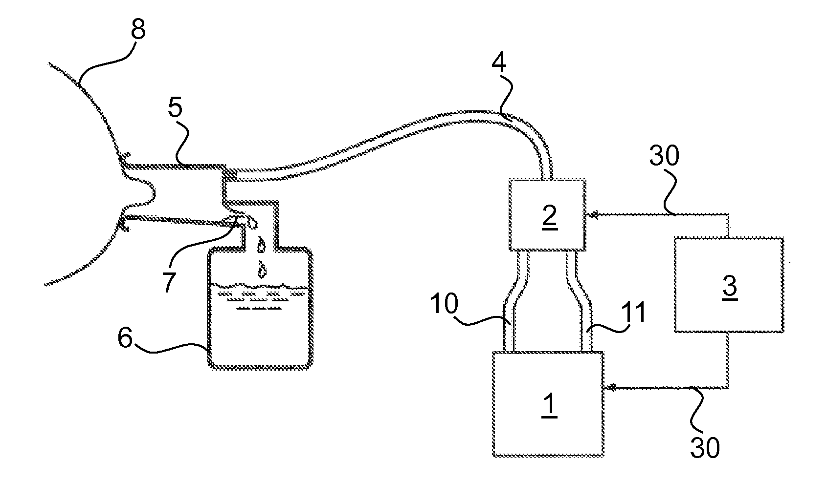
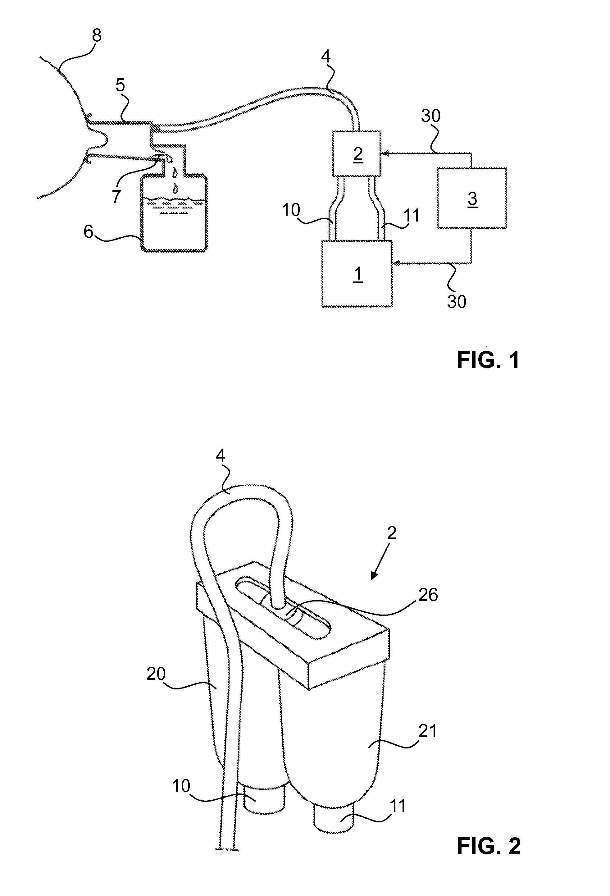
[0052]FIG. 1 shows a schematic breast pump unit. However, the instruction according to the invention can also be applied to other suction pumps, in particular to drainage pumps. The suction pump unit comprises a suction pump 1, also referred to as vacuum aggregate. The suction pump 1 comprises a suction or a vacuum port and an exhaust for ventilating the suction pump 1. A suction line 10 is hooked up to the suction connection, while a pressure line 11 is hooked up to the exhaust. These two lines 10, 11 lead to a switching valve 2, also referred to as actuator. The suction pump 1 and the switching valve 2 are connected to each other by an electronic controller 3. The connecting lines are depicted schematically, and marked with reference number 30.

[0053]An output line 4 leads from the switching valve 2 to a breast shield 5, which is connected with a milk collection container 6. Usually situated between the milk collection container 6 and breast shield 5 is a check valve 7, which limit...


PUM


Abstract

A suction pump unit comprises a vacuum port, an excess pressure port and a switching valve. The switching valve comprises a valve body with two inputs, wherein a first of the inputs is connected with the vacuum port, and a second of the inputs is connected with the excess pressure port. The switching valve further comprises an output with a through hole, wherein the output can be moved relative to the inputs from the first input to the second input and back, as a result of which the through hole alternately establishes a fluid-communicating connection with one of the inputs. The through hole of the output is released and ventilated during at least part of the movement between the two inputs. This suction pump unit permits passive and active ventilation of an output line connected with the output.

Description

CROSS-REFERENCE TO RELATED APPLICATIONS[0001]This application claims the benefit of Swiss Patent Application Serial No. 0474 / 12 filed Apr. 4, 2012, the contents of which are fully incorporated herein by reference.TECHNICAL AREA[0002]The present invention relates to a suction pump unit as well as to a method for operating a suction pump unit. The suction pump serves in particular for use as a breast pump for extracting human breast milk.BACKGROUND[0003]Suction pump units are sufficiently known in prior art. They are used for extracting breast milk, but also in the medical field for extracting body liquids or fluids. Examples for the latter include extraction processes during and after surgical procedures, wound drainage, thorax drainage, and the suctioning of body fat.[0004]While pumping breast milk, a vacuum pump is used to create a vacuum in a breast shield applied to the mother's breast, which causes the breast milk to be extracted from the breast. In order to enable as painless a...

Claims


Application Information

Patent Timeline
Patent Type & Authority Applications(United States)
IPC IPC(8): A61M1/06
CPCA61M1/06A61M1/0066A61M2039/224A61M1/0037A61M1/75A61M1/80A01J5/04
Inventor FELBER, ARMIN
Owner MEDELA HLDG AG
Why Eureka
Try Eureka