Distributor tray for offshore gas/liquid contact column
Active Publication Date: 2013-10-24
INST FR DU PETROLE
View PDF2 Cites 9 Cited by
Summary
Abstract
Description
Claims
Application Information
AI Technical Summary
This helps you quickly interpret patents by identifying the three key elements:
Problems solved by technology
Method used
Benefits of technology
Benefits of technology
The invention relates to a distributor tray for a gas / liquid contact column that includes gas passage means and liquid passage means. The gas passage means are distributed in a way that they form compartments to decrease the liquid guard height under the effect of wave motion to ensure proper supply and good distribution of the liquid over the entire tray. The tray also includes multiple gas passage means with the means allowing gas to flow between them. The dimensions of the gas passage means are defined, and the invention also relates to an offshore gas / liquid contact column, a gas treatment unit, a CO2 capture unit, an offshore floating barge, and a method of manufacturing the tray. The technical effects of the invention include improved gas / liquid contact, reduced liquid guard height, improved gas distribution, and improved gas treatment and CO2 capture.
Problems solved by technology
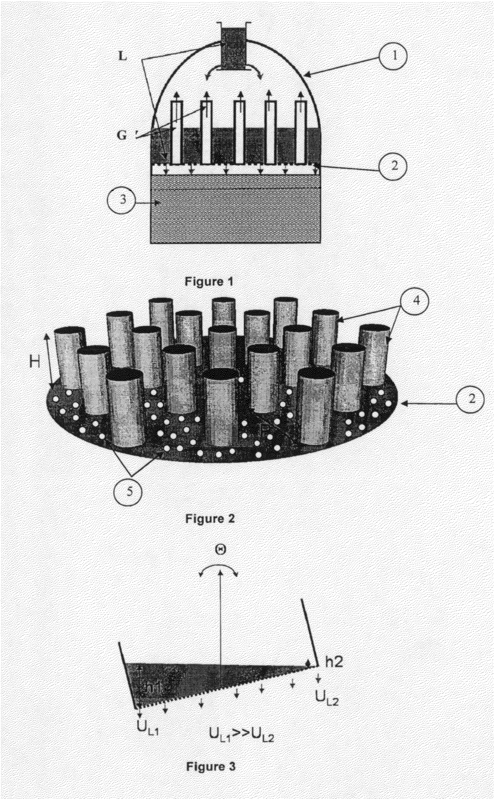
Under such conditions, the operation of conventional distributor trays equipped with chimneys (FIG. 2) can be greatly disturbed.
When tray (2) is inclined under the effect of the wave motion (FIG. 3), the height of the liquid level is no longer uniform on the distributor tray (h1>h2), which causes an imbalance in the distribution of liquid at the inlet of gas / liquid contactor (3).
The distribution quality and thus the efficiency of the column are greatly impacted.
This poor distribution, if it is not controlled, can substantially degrade the performances of the column.
A great liquid guard height (around 0.6 m) would be necessary to make up for these effects, which means bulk and weight increase, which is not suitable for offshore units.
These distributors are generally insensitive to the effects of the wave motion and they generate a good distribution quality, but they are very bulky.
However, this option remains cumbersome because it requires two distributors.
However, the compartments do not communicate with one another, resulting in the liquid not being evenly distributed in the compartments.
The parallelism of the chimneys does not allow proper supply and good distribution of the liquid over the entire tray.
Method used
Image
Click on the blue label to locate the original text in one second.
Reading with bidirectional positioning of images and text.
Examples
example 1
Properties of the Standard Tray (Prior Art of FIG. 2)
[0098]Diameter of the distributor tray is 4150 mm.
Properties of the Tray According to the Invention (Chimney Distribution According to the Embodiment of FIG. 5)
[0110]Diameter of distributor tray (2) is 4150 mm.
[0111]Height of gas chimneys (4) is 700 mm.
[0112]Distance L1 is 0 mm.
[0113]Distance L2 is 82 mm.
[0114]Distance L3 is 50 mm.
[0115]Distance Z is 925 mm.
[0116]FIGS. 7, 8 and 9 show the evolution of the liquid guard (gas / liquid interface) on the distributor when it is subjected to wave motions, for examples 1, 2 and 3 respectively. The results are obtained from dynamic CFD type calculations. The figures show different instants corresponding to different extreme positions. FIGS. 7a), 8a) and 9a) show the trays in a horizontal position (θ=0°); FIGS. 7b), 8b) and 9b) show the trays in a first extremal position (θ=5°) corresponding to a wave motion; and FIGS. 7c), 8c) and 9c) show the trays in a second extremal position opposite the first extremal position (θ=−5°). The right part of FIGS. 7, 8 and 9 illustrates the variation of the l...
PUM
Property
Measurement
Unit
Length
aaaaa
aaaaa
Length
aaaaa
aaaaa
Length
aaaaa
aaaaa
Abstract
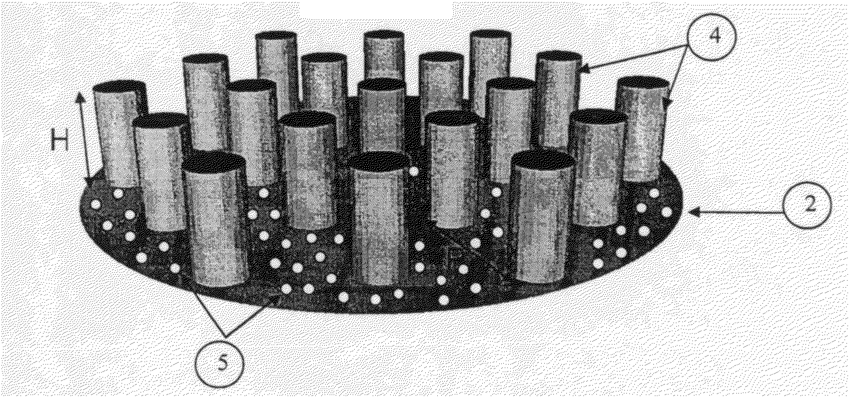
The invention is a distributor tray for a column (1) for heat and / or material exchange between a gas (G) and a liquid (L), comprising at least one means providing passage of the gas through the tray (2). The means has at least one wall (4), defining on the surface of the tray (2) compartments (8) of substantially identical surface areas. Each compartment comprises at least one means (5) allowing passage of the liquid through the tray (2). The invention also has application to a gas / liquid contact column, a gas treatment unit, a CO2 capture unit, a distillation unit, an offshore floating barge comprising such a distributor tray and a method of manufacturing the tray.
Description
CROSS-REFERENCE TO RELATED APPLICATION[0001]Reference is made to French patent application Ser. No. 12 / 01.143, filed on Apr. 18, 2013, and a copending related application entitled “PARTITIONED DISTRIBUTOR TRAY FOR OFFSHORE GAS / LIQUID CONTACT COLUMN.” filed on Apr. 17, 2013 (Attorney Ref: 612.53035×00) which applications are incorporated herein by reference in their entirety.BACKGROUND OF THE INVENTION[0002]1. Field of the Invention[0003]The present invention relates to offshore gas / liquid contact columns, and more particularly to offshore gas treatment, CO2 capture, dehydration or distillation units.[0004]2. Description of the Prior Art[0005]Offshore gas treatment and / or CO2 capture units using amine wash processes comprise liquid or gaseous fluid absorption and regeneration columns. These columns operate under counter-current or co-current gas / liquid flow conditions and, for example, are installed on vessels, floating barges or offshore platforms, of FPSO (Floating Production, Stor...
Claims
Application Information
Patent Timeline
Application Date:The date an application was filed.
Publication Date:The date a patent or application was officially published.
First Publication Date:The earliest publication date of a patent with the same application number.
Issue Date:Publication date of the patent grant document.
PCT Entry Date:The Entry date of PCT National Phase.
Estimated Expiry Date:The statutory expiry date of a patent right according to the Patent Law, and it is the longest term of protection that the patent right can achieve without the termination of the patent right due to other reasons(Term extension factor has been taken into account ).
Invalid Date:Actual expiry date is based on effective date or publication date of legal transaction data of invalid patent.

