

Test coaxial connector
- Summary
- Abstract
- Description
- Claims
- Application Information
AI Technical Summary
Benefits of technology
Problems solved by technology
Method used
Image

Examples
first embodiment
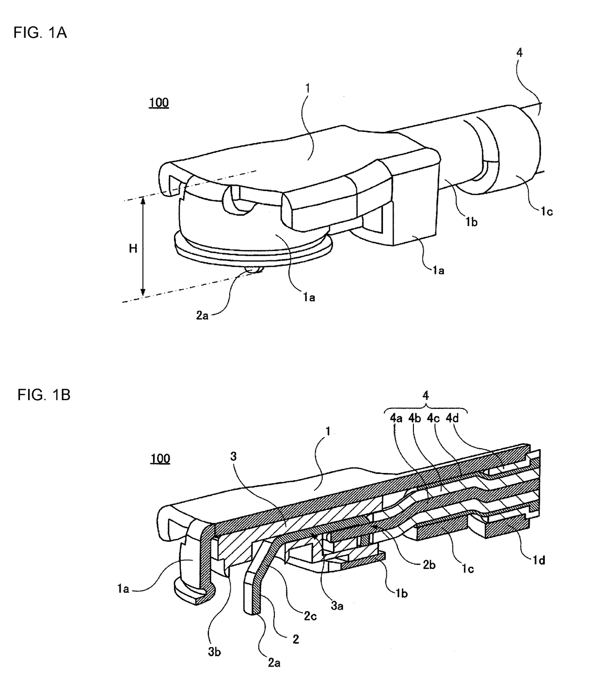
[0032]FIGS. 1A and 1B show a test coaxial connector 100 according to a first embodiment. FIG. 1A is a perspective view of the test coaxial connector 100, and FIG. 1B is an exploded perspective view of the test coaxial connector 100.
[0033]The test coaxial connector 100 includes a conductive housing 1. The housing 1 is produced from, for example, beryllium copper. A tubular fitting portion 1a for fitting to a switch-equipped connector (not shown) is formed at a front portion of the housing 1.
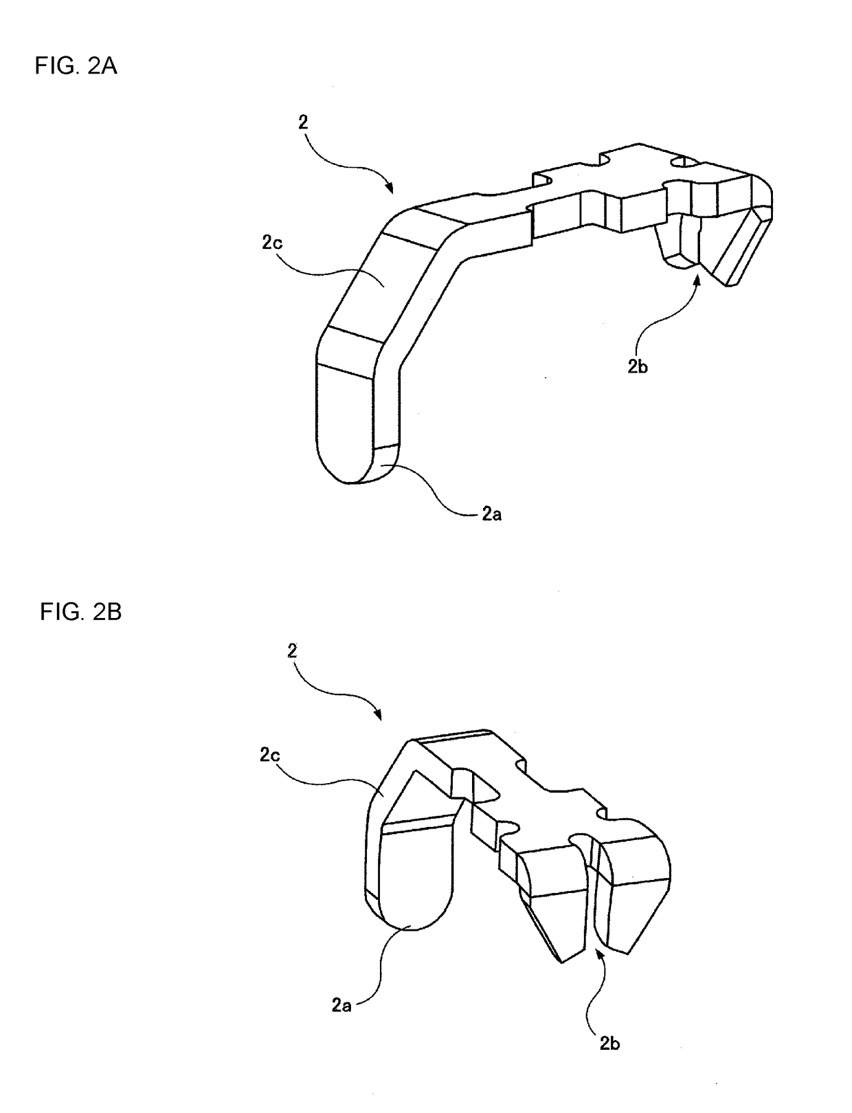
[0034]The test coaxial connector 100 includes a conductive probe (central terminal) 2. FIGS. 2A and 2B show the probe 2. FIG. 2A is a perspective view of the probe 2 as seen from the front side, and FIG. 2B is a perspective view of the probe 2 as seen from the rear side.
[0035]The probe 2 is produced from, for example, one plate-shaped beryllium copper. The probe 2 has a contact 2a at a front portion thereof. In addition, the probe 2 has a cut 2b as a connection portion for connecting a central con...
second embodiment
[0055]FIG. 5 shows a probe 22 of a test coaxial connector according to the second embodiment.
[0056]In the probe 22, a zigzag portion 22c is formed between a contact 22a and a cut 22b for connecting the shield conductor 4c of the coaxial cable 4. The probe 22 has elasticity (spring property) since the zigzag portion 22c is formed in the probe 2.
third embodiment
[0057]FIG. 5B shows a probe 32 of a test coaxial connector according to the third embodiment.
[0058]In the probe 32, a rounded bent portion 32c is formed between a contact 32a and a cut 32b. The probe 32 has elasticity since the rounded bent portion 32c is formed in the probe 22.
PUM
 Abstract
Description
Claims
Application Information