Blind Nut and Mounting Structure Thereof

Inactive Publication Date: 2018-02-08
NEWFREY
View PDF3 Cites 2 Cited by
  • Summary
  • Abstract
  • Description
  • Claims
  • Application Information

AI Technical Summary

Benefits of technology

[0040]The diameter-enlarged member of the main body tubular member is preferably enlarged right above the lower edge surface of the main body tubular member. When the diameter-enlarged member of the main body tubular member is enlarged right above the lower edge surface of the main body tubular member, the height of the main body can be decreased; thus, the height of the blind nut can be decreased as well.
[0041]It is preferred that the male screw on the shank of a bolt be engaged wi

Problems solved by technology

Moreover, uselessly utilizing a long bolt is no longer necessary.
Moreover, it is possible that the lower portion of the female screw of the female screw me

Method used


Image

  • Blind Nut and Mounting Structure Thereof
  • Blind Nut and Mounting Structure Thereof
  • Blind Nut and Mounting Structure Thereof

Examples


Example

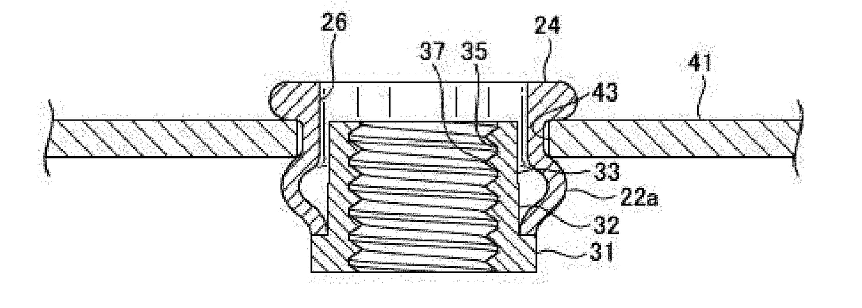
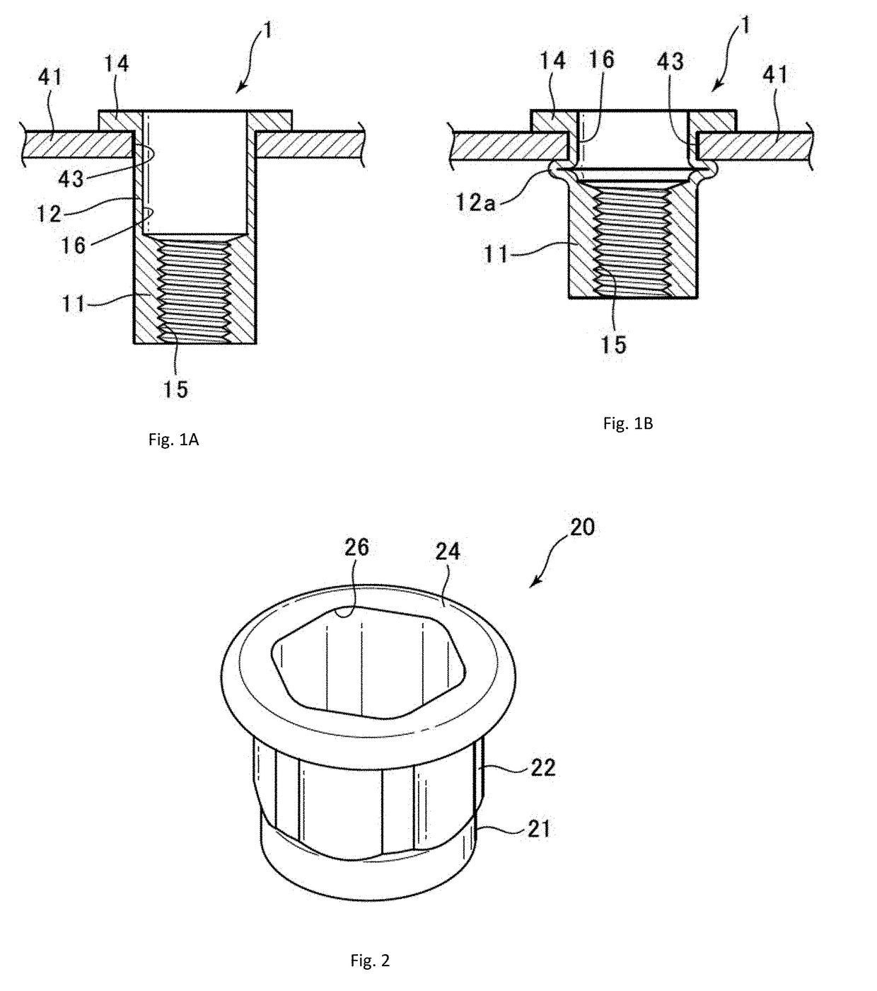
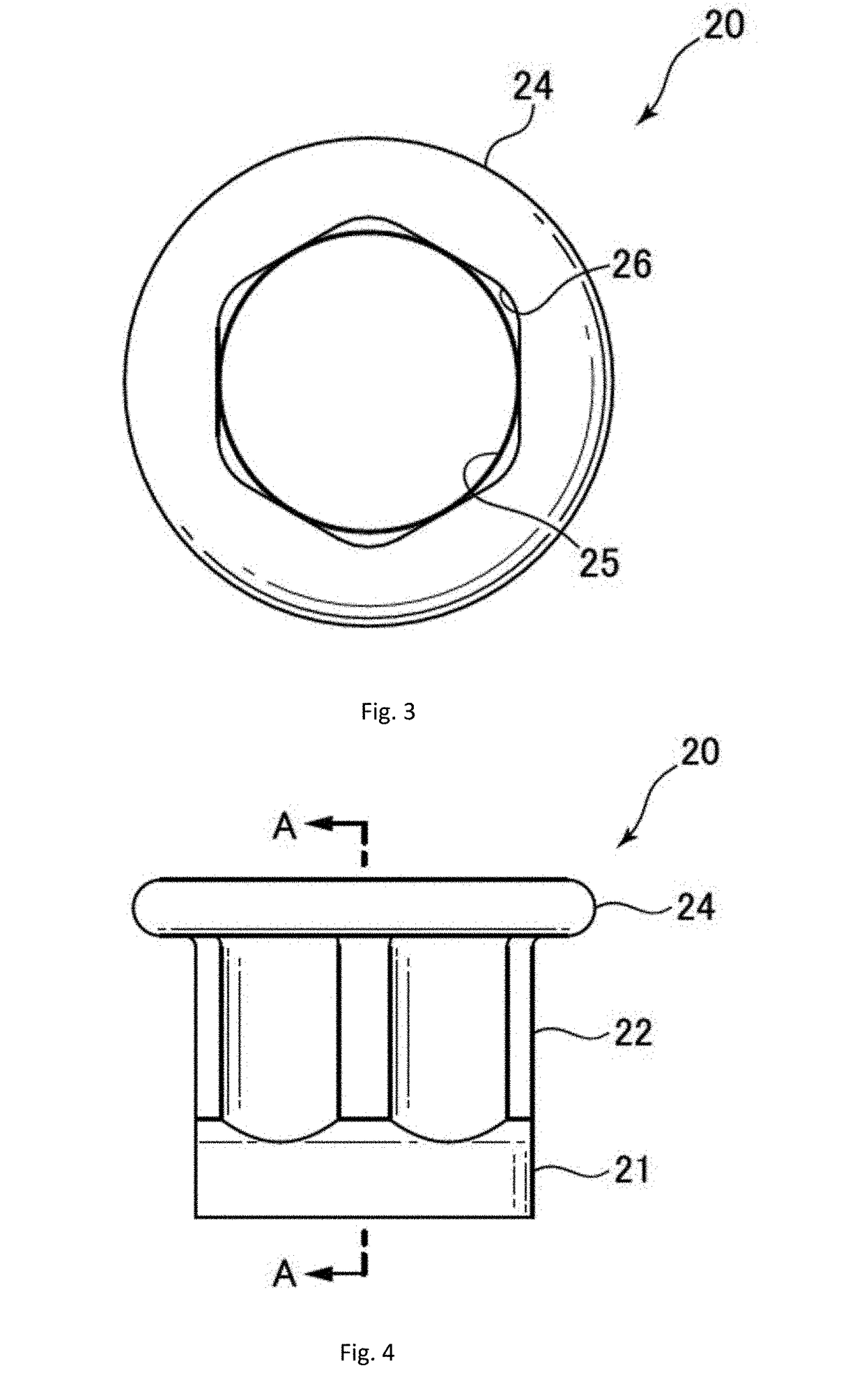
[0061]An explanation of blind nut 10 of a working example of the present invention shall be given below with reference to the drawings. FIGS. 2 to 6 show main body 20 of blind nut 10, and FIGS. 7 to 10 show nut member 30 of blind nut 10. FIG. 11 shows the state in which main body 20 and nut member 30 are not yet coupled, and FIGS. 12 to 15 show the state in which main body 20 and nut member 30 are coupled. FIG. 16 shows the state in which blind nut 10 is mounted onto mounted member 41, and FIG. 17 shows the state in which mounting member 42 is mounted by means of bolt 45 onto blind nut 10 which has been mounted onto mounted member 41.

[0062]Blind nut 10 of a working example of the present invention comprises main body 20, which is formed with a plastically deformable material such as metal and the like; and nut member 30, which is formed with a rigid material such as metal and the like. As shown in FIG. 11, nut member 30 is inserted from the lower side of main body 20, and the lower ...


PUM


Abstract

A Blind nut may be mounted on a hole of a mounted member. The blind nut includes a main body with a plastically deformable material and a nut member with a relatively harder material. The main body has a cylindrical first tubular portion and a second hexagonal and cylindrical tubular portion provided adjacent to first tubular member. A flange is provided adjacent the second tubular member. Nut member includes a short cylindrical nut base member. Nut tubular members are adjacent nut base member and have a smaller outer diameter than that of the nut base member. A female threaded pass-through hole extends across the length of the nut member. The nut cylinder members are inside the first tubular member and the second tubular member; and the lower edge of the main body tubular member is in contact with a step member of the nut base member and welded thereto.

Description

CROSS-REFERENCE TO RELATED APPLICATIONS[0001]This is a continuation application of PCT application PCT / JP2016 / 055005 filed Feb. 22, 2016, which claims priority from Japanese Patent Application No. 2015-086518, filed Apr. 21, 2015, the disclosure of which is incorporated herein by reference in its entirety.FIELD OF THE INVENTION[0002]The present invention relates to a blind nut and a mounting structure thereof, and in particular to a blind nut wherein the post-fastening height is short as well as a mounting structure wherein the blind nut is mounted onto a mounted member thereof.BACKGROUND OF THE INVENTION[0003]A blind nut comprises a female screw member in which a female screw is formed, a hollow tubular member is provided adjacent to the female screw member and a tubular flange which has an opening on one end. When the tubular member of the blind nut is inserted into the mounting hole of the mounted member to cause the flange to be in contact with the surface of the mounted member,...

Claims


Application Information

Patent Timeline
IPC IPC(8): F16B37/04F16B5/02
CPCF16B37/04F16B5/02F16B37/067
Inventor MAKINO, TAKANORISAKODA, KANJI
Owner NEWFREY
Why Eureka
Try Eureka