Probe card

Inactive Publication Date: 2007-08-02
MICROELECTRONICS TECH INC
View PDF3 Cites 1 Cited by
  • Summary
  • Abstract
  • Description
  • Claims
  • Application Information

AI Technical Summary

Benefits of technology

[0008]The secondary object of the present invention is to provide a probe card, which has more spring for choice.
[0009]The third

Problems solved by technology

It may not build an electrical connection between the probe card and the integrated circuit while the probes with different pressures pressed the pads that makes the probe card can not read the actual electrical properties of the integrated circuit.
Type

Method used


Image

  • Probe card
  • Probe card
  • Probe card

Examples


Example

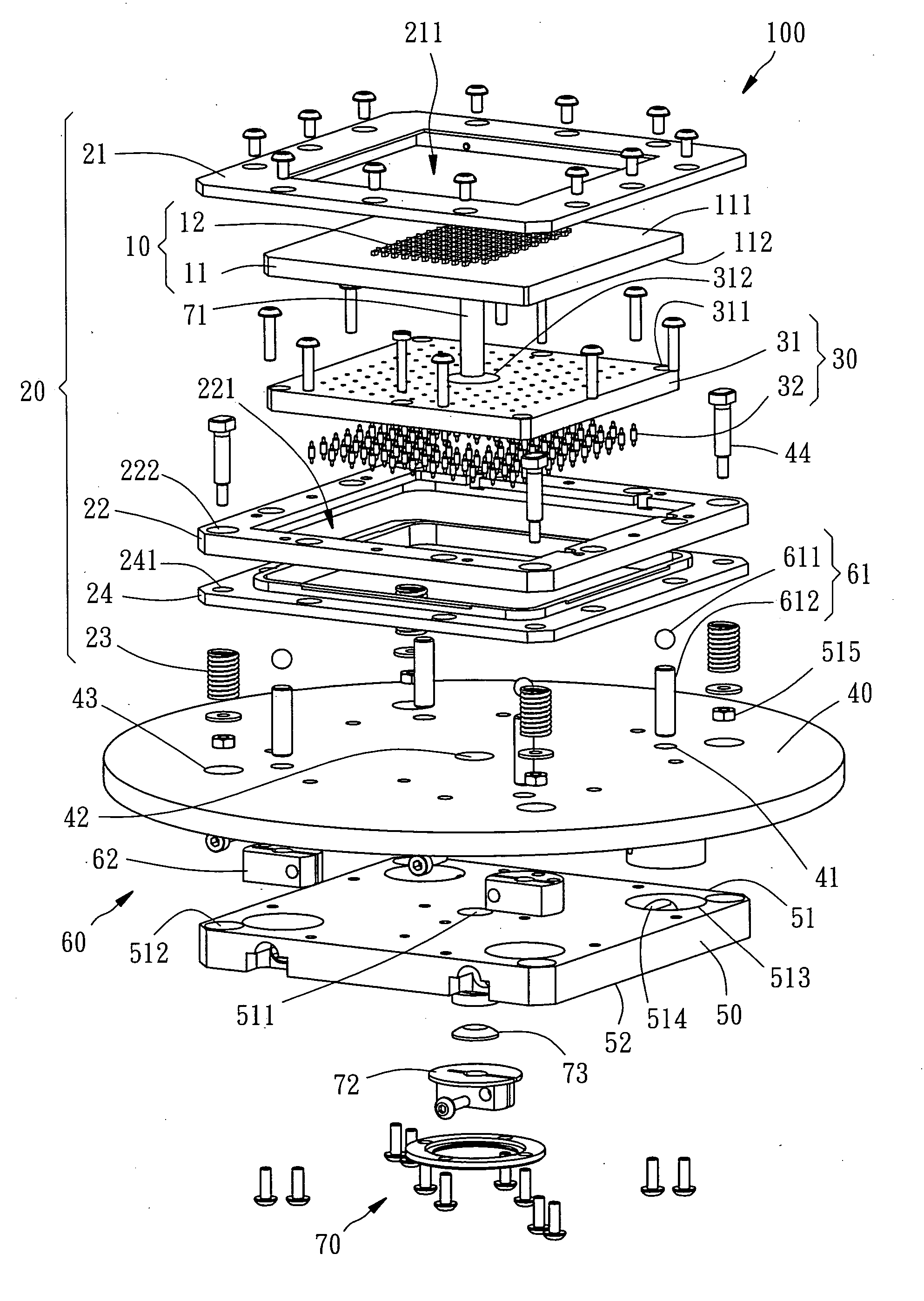
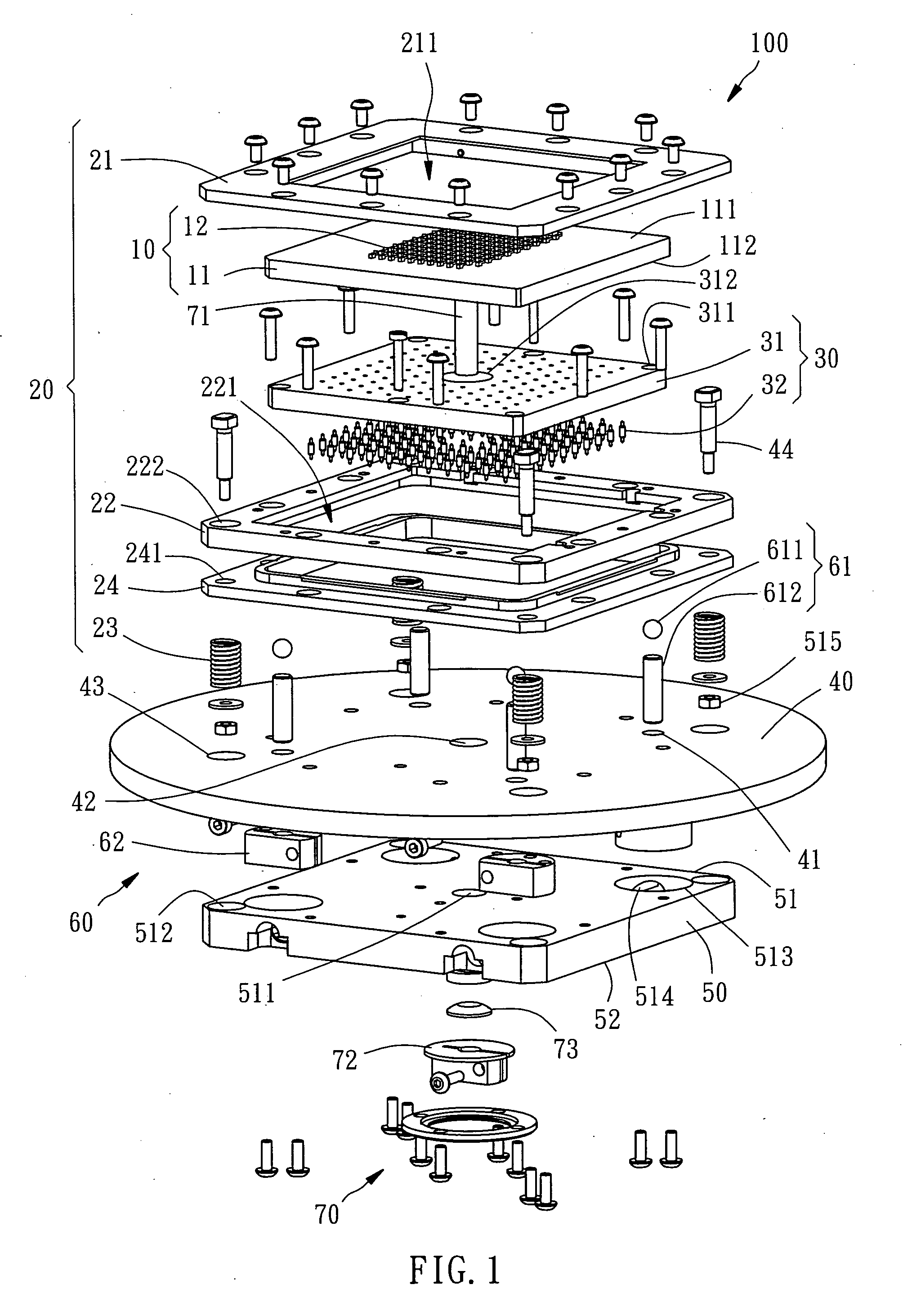
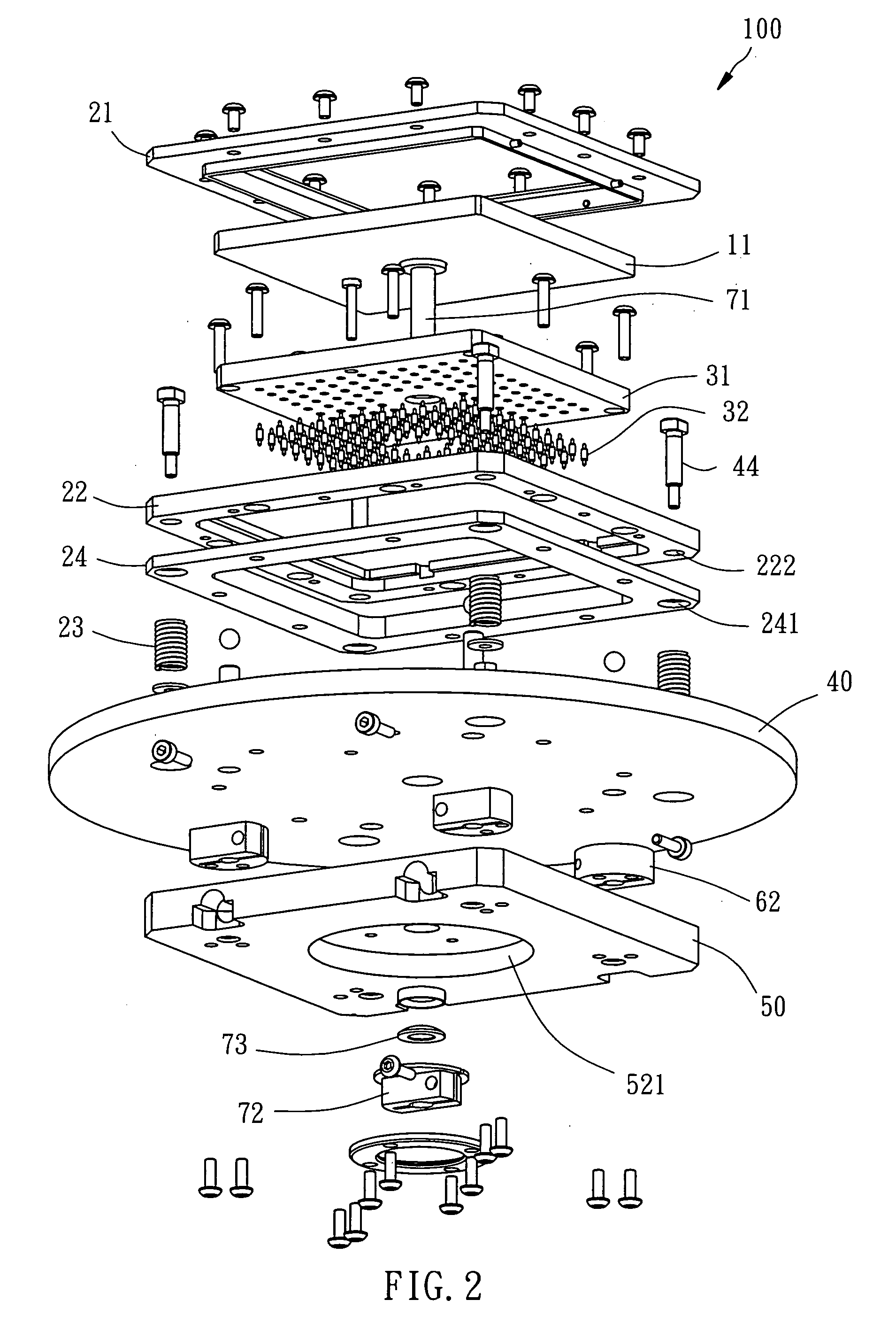
[0013]As shown in FIGS. 1 to 3, a probe card 100 of the preferred embodiment of the present invention includes a probe assembly 10, an elastic support assemble 20, an elastic connection assembly 30, a circuit board 40, a substrate 50, a plurality of level maintaining assemblies 60 and a turning secure assembly 70.

[0014]The probe assembly 10 includes an electrical signal transform board 11 and a plurality of probes 12. The electrical signal transform board 11, which is an insulating rectangular substrate in the present embodiment, having a first electrical signal side 111, a second electrical signal side 112 opposite to the first electrical signal side 111 and a conductor pattern (not shown) therein for electrical connection of first pads (not shown) on the first electrical signal side 111 and second pads (not shown) on the second electrical signal side 112. The probes 12 are flexible metallic member with ends connected to the first pads of the first electrical signal side 111 and th...


PUM


Abstract

A probe card mainly includes a circuit board, a probe assembly, an elastic support assembly, a plurality of level maintaining assemblies and a turning secure assembly. The circuit board has pads and spring bores. The probe assembly has a electrical signal transform board and probes on it. The elastic support assembly has a fixed plate, a locking plate and a plurality of springs. The springs are received in the spring bores of the circuit board to urge the electrical signal transform board for absorption of a height difference of the electrical signal transform board when the electrical signal transform board is inclined.

Description

BACKGROUND OF THE INVENTION[0001]1. Field of the Invention[0002]The present invention relates to a testing device of integrated circuit and more particularly, to a probe card capable of maintaining horizontal of the probe assembly.[0003]2. Description of the Related Art[0004]Integrated circuits on a wafer have to pass electrical test and those passing the test are picked out for the following package procedure to form chips. The chips are tested again to pick out defective products. In the rear-end process of integrated circuit, there are several testing procedures of the electrical properties of the integrated circuits or chips. In the present electrical test, a probe card is provided which includes several probes contacted with the circuits for testing its electrical properties.[0005]In the electrical test, planes on tips of the probes has to be substantially parallel to planes of pads of the integrated circuit that causes the probes with the same pressure press the pads of the in...

Claims


Application Information

Patent Timeline
IPC IPC(8): G01R31/02
CPCG01R1/07307H01L22/00
Inventor FAN, HORNG-KUANG
Owner MICROELECTRONICS TECH INC
Why Eureka
Try Eureka