
Space conditioning system with hot gas reheat, and method of operating the same

Active Publication Date: 2013-10-31
MODINE MFG CO
View PDF12 Cites 6 Cited by
  • Summary
  • Abstract
  • Description
  • Claims
  • Application Information

AI Technical Summary

Benefits of technology

The invention is a space conditioning system that uses a compressor, condenser, and hot gas reheat section. The system includes one or more modulating valves that can selectively direct refrigerant through different outlets. The system can also include a control valve that can be opened or closed to control the flow of refrigerant. The technical effect of this invention is that it allows for more efficient and precise control of the refrigerant flow through the system, resulting in improved performance and efficiency.

Problems solved by technology

In addition to imposing discomfort on occupants, high humidity levels can lead to the growth of molds, fungi, and other non-desirable organisms.
When the outside relative humidity is elevated, such high fresh air ventilation rates coupled with the desire for low internal humidity levels lead to a high latent heat load on the space conditioning system.

Method used


Image

  • Space conditioning system with hot gas reheat, and method of operating the same
  • Space conditioning system with hot gas reheat, and method of operating the same
  • Space conditioning system with hot gas reheat, and method of operating the same

Examples


Embodiment Construction

[0020]Before any embodiments of the invention are explained in detail, it is to be understood that the invention is not limited in its application to the details of construction and the arrangement of components set forth in the following description or illustrated in the following drawings. The invention is capable of other embodiments and of being practiced or of being carried out in various ways. Also, it is to be understood that the phraseology and terminology used herein is for the purpose of description and should not be regarded as limiting. The use of “including,”“comprising,” or “having” and variations thereof herein is meant to encompass the items listed thereafter and equivalents thereof as well as additional items. Unless specified or limited otherwise, the terms “mounted,”“connected,”“supported,” and “coupled” and variations thereof are used broadly and encompass both direct and indirect mountings, connections, supports, and couplings. Further, “connected” and “coupled”...


PUM


Abstract

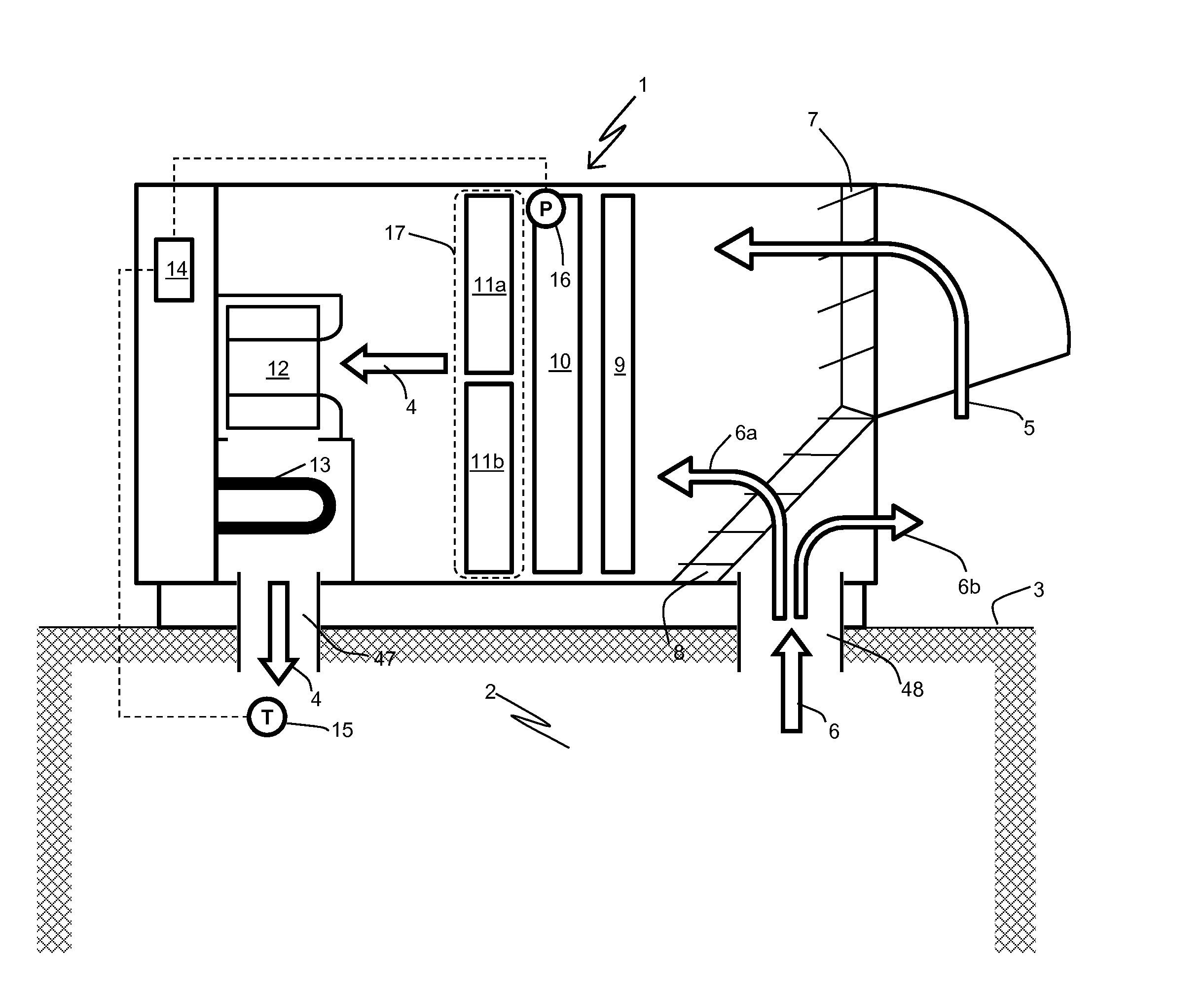
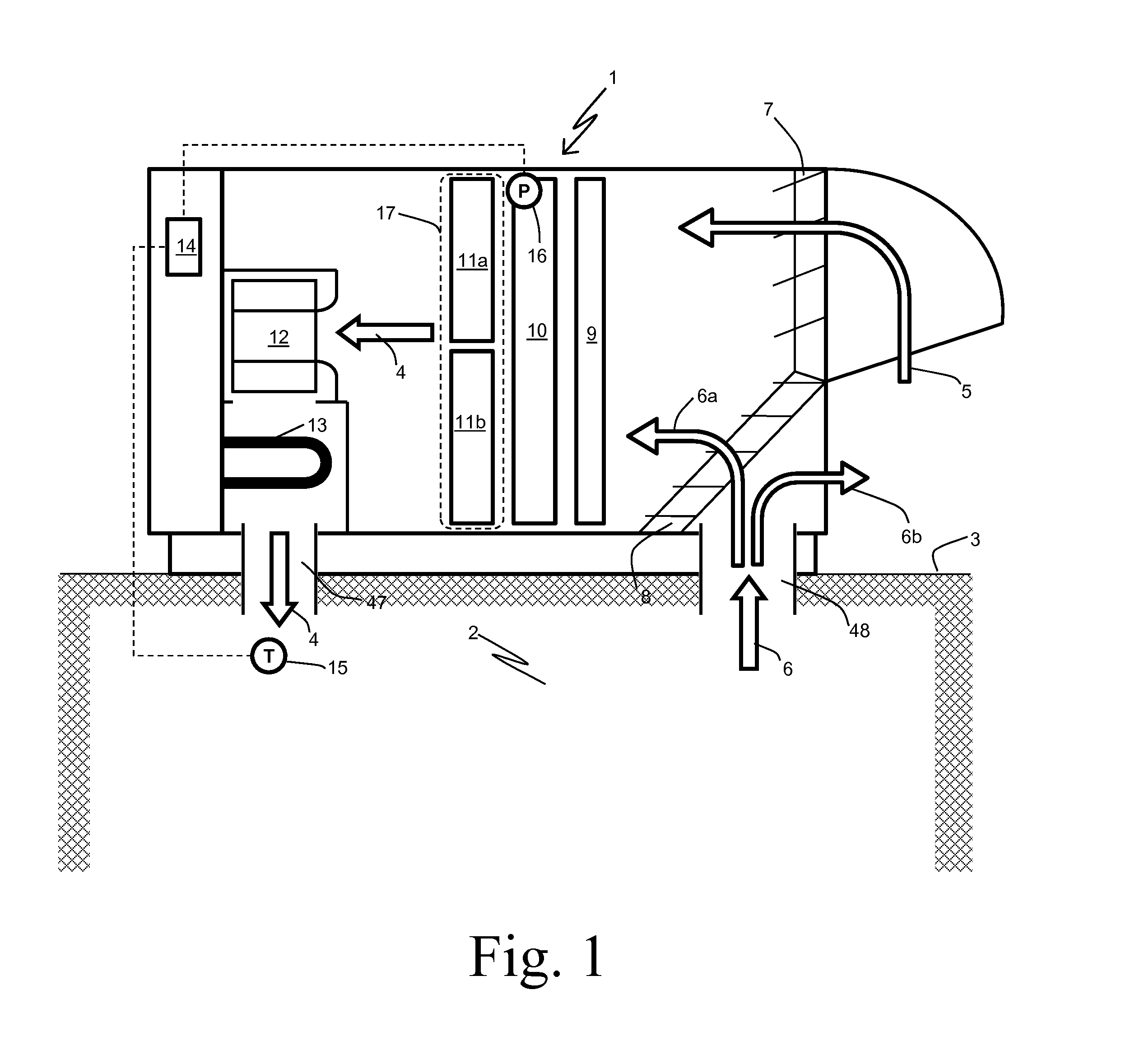
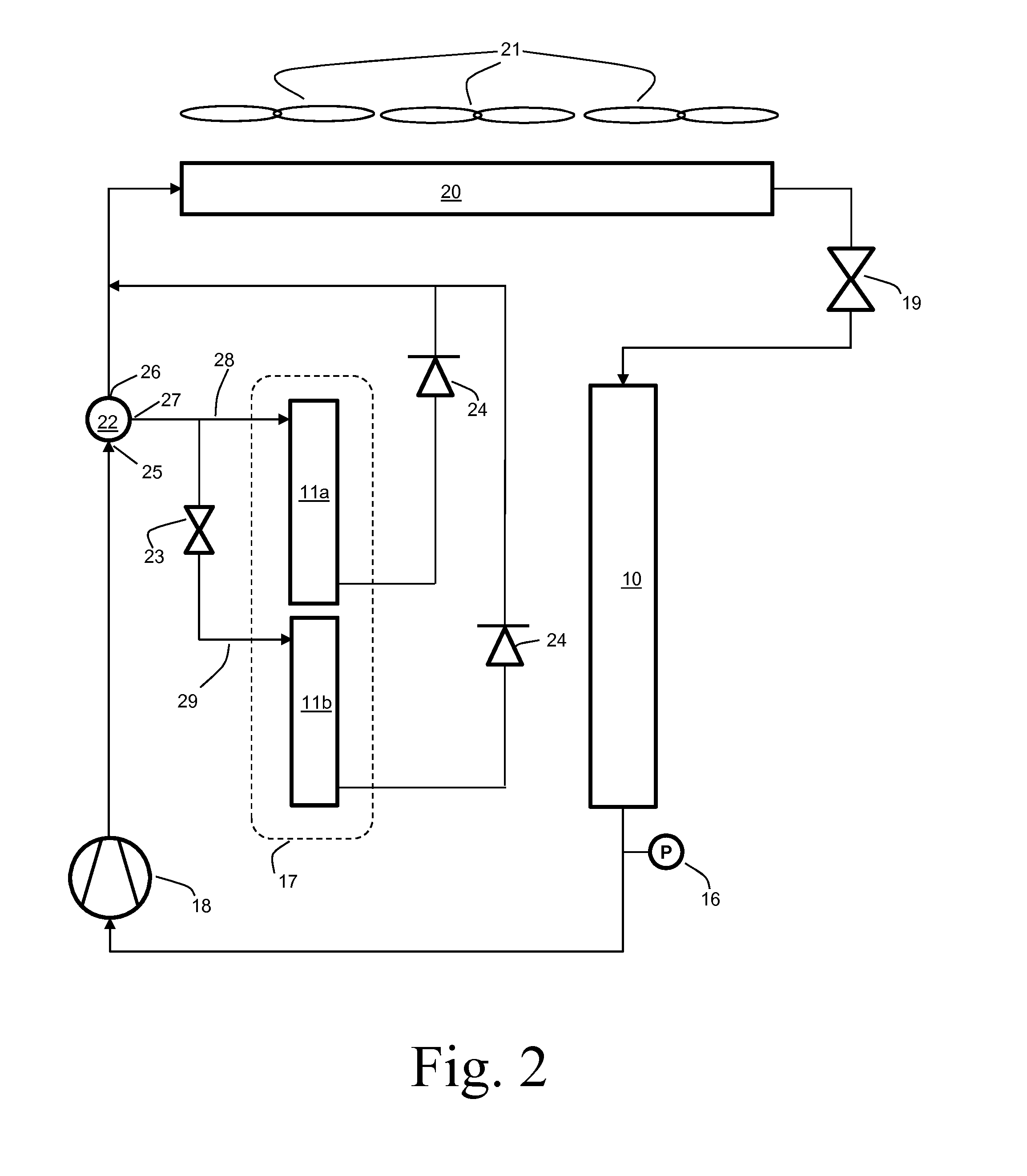
A space conditioning system includes a hot gas reheat section and one or more modulating valves to direct a percentage of refrigerant flow to the hot gas reheat section. The hot gas reheat section includes multiple refrigerant circuits arranged in parallel. A control valve is used to allow the refrigerant to flow through selected ones of the multiple refrigerant circuits in response to the percentage of refrigerant flow directed to the hot gas reheat section, thereby varying the internal volume of the hot gas reheat section available to the refrigerant. Refrigerant charge hold-up within the hot gas reheat section can thereby be minimized.

Description

BACKGROUND[0001]Space conditioning systems are used to maintain desirable levels of temperature, humidity, and fresh air inside of buildings, vehicles, and the like. Of particular importance in the proper operation of such a system is maintaining proper humidity levels. In addition to imposing discomfort on occupants, high humidity levels can lead to the growth of molds, fungi, and other non-desirable organisms. These concerns lead to the ability of the space conditioning system to remove humidity from the air (referred to as latent heat load) being a major design consideration.[0002]At the same time, concerns over poor indoor air quality caused by inadequate air exchange have led to the desire for higher fresh air ventilation rates. When the outside relative humidity is elevated, such high fresh air ventilation rates coupled with the desire for low internal humidity levels lead to a high latent heat load on the space conditioning system.[0003]The typical method by which large amoun...

Claims


Application Information

Patent Timeline
IPC IPC(8): F25B1/00
CPCF25B49/02F24F3/153F25B2400/0403F25B41/20
Inventor HUA, YI
Owner MODINE MFG CO
Learn More