Surgical clip applier

a clip applier and surgical technology, applied in the field of surgical clip appliers, can solve the problems of many times being defeated the lockout mechanism, trauma to the tissue, and serious damage to the tissue or vessel

Active Publication Date: 2013-10-31
COVIDIEN LP
View PDF1 Cites 87 Cited by
  • Summary
  • Abstract
  • Description
  • Claims
  • Application Information

AI Technical Summary

Benefits of technology

The clip applier described in this patent has a mechanism called a ratchet that prevents the drive channel from being fully actuated until the handles are fully pressed. This mechanism includes a rack with teeth and a pawl with teeth that are engaged with the rack. As the drive channel is moved back and forth, the teeth on the rack pass over the teeth on the pawl, allowing the ratchet to engage and hold the drive channel in place. This mechanism ensures the clip applier operates only when the user presses the handles, reducing the chance of accidental triggering.

Problems solved by technology

These lockout mechanisms prevent closure of the jaws about tissue, which can traumatize the tissue and perhaps cause serious damage to the tissue or vessel when a clip is not present in the jaws.
However, many of the prior art instruments provide a lockout mechanism which interferes with the closure of the jaws, and upon the application of enough force to the handles, the lockout mechanism many times may be defeated.
In order to prevent this, complex mechanisms are often provided, resulting in increased cost of manufacture of the instrument.
In addition, many of the prior art instruments provide complex mechanical arrangements for closing the jaws while simultaneously preparing for feeding the next clip into the jaws after the clip positioned between the jaws is deformed and then released.
These complex mechanisms, such as that shown in U.S. Pat. No. 5,431,668 to Burbank, III et al., require numerous parts which increases the cost of manufacture, as well as increasing the time it takes to assemble each instrument.
This arrangement typically requires additional moving parts, also tending to increase the cost of manufacture and increase the time of assembly.

Method used


Image

  • Surgical clip applier
  • Surgical clip applier
  • Surgical clip applier

Examples


Embodiment Construction

[0084]Embodiments of surgical clip appliers in accordance with the present disclosure will now be described in detail with reference to the drawing figures wherein like reference numerals identify similar or identical structural elements. As shown in the drawings and described throughout the following description, as is traditional when referring to relative positioning on a surgical instrument, the term “proximal” refers to the end of the apparatus which is closer to the user and the term “distal” refers to the end of the apparatus which is further away from the user.

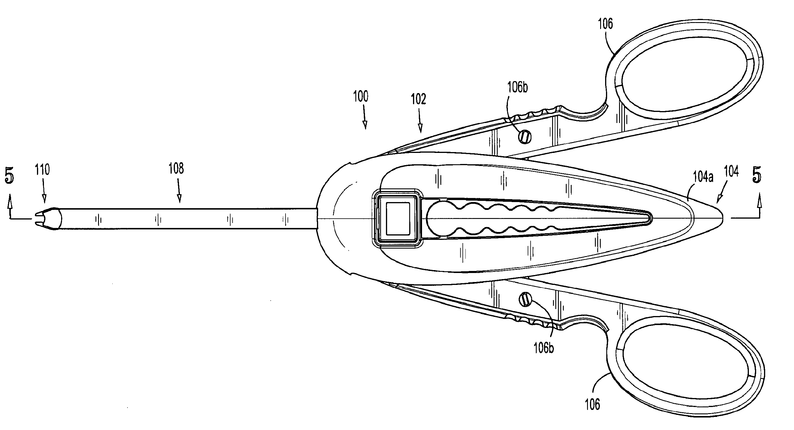
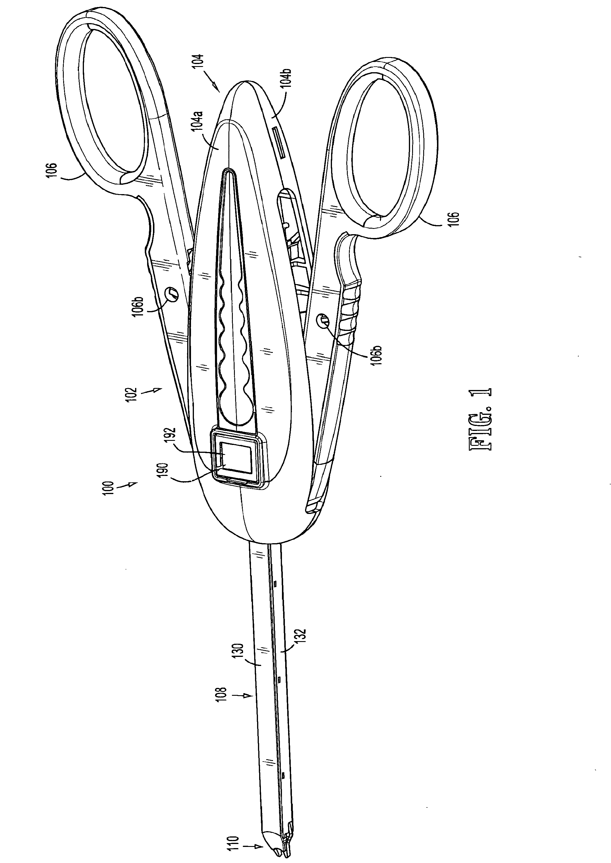
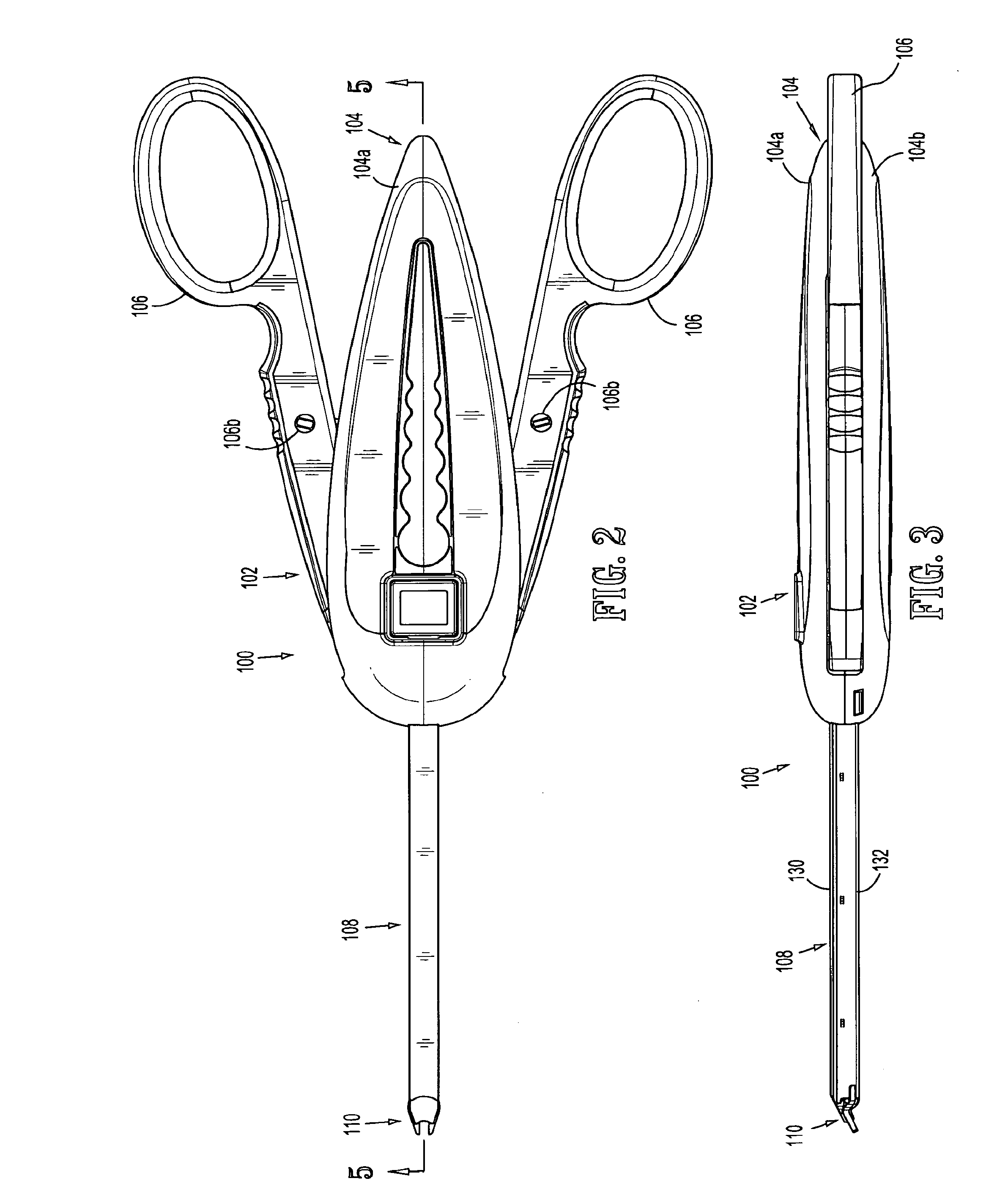
[0085]Referring now to FIGS. 1-5, a surgical clip applier in accordance with an embodiment of the present disclosure is generally designated as 100. Surgical clip applier 100 generally includes a handle assembly 102 and a handle assembly 102 including a housing 104 having an upper housing half 104a and lower housing half 104b. Handle assembly 102 further includes a pair of handles 106 pivotably secured to housing 104 a...


PUM


Abstract

A surgical clip applier is provided including a housing; a pair of handles; a channel assembly extending from the housing; a clip carrier disposed within said channel assembly and defining a channel and a plurality of windows; a wedge plate slidably disposed within said channel assembly and being operatively connected to said handles, said wedge plate including a plurality of apertures formed along a length thereof; a plurality of clips slidably disposed within said channel of said clip carrier; and a clip follower slidably disposed within said channel of said clip carrier at a location proximal of said plurality of clips. The clip follower is configured and adapted for selective engagement with said windows of said clip carrier and said apertures of said wedge plate to distally urge said plurality of clips relative to said clip carrier upon a distal advancement of said wedge plate.

Description

CROSS-REFERENCE TO RELATED APPLICATION[0001]The present application is a Continuation Application which claims the benefit of and priority to U.S. patent application Ser. No. 12 / 595,318, filed on Jan. 21, 2010, which is a National Stage Application of PCT / US2008 / 059859, filed Apr. 10, 2008, under 35 U.S.C. §371(a), which claims the benefit of and priority to U.S. Provisional Patent Application Ser. No. 60 / 922,946, filed on Apr. 11, 2007, the entire content of each of which is incorporated herein by reference.BACKGROUND[0002]1. Technical Field[0003]The present application relates to surgical clip appliers, and in particular relates to instruments having a plurality of clips for applying the clips to body tissues and vessels during surgical procedures.[0004]2. Discussion of Related Art[0005]Surgical clip appliers are known in the art and have increased in popularity among surgeons by offering an alternative to conventional suturing of body tissues and vessels. Typical instruments are ...

Claims


Application Information

Patent Timeline
Patent Type & Authority Applications(United States)
IPC IPC(8): A61B17/128
CPCA61B17/128A61B17/1285A61B2017/00407A61B2090/038A61B2090/0803A61B90/03A61B90/08A61B2017/00734
Inventor ZERGIEBEL, EARL M.WHITFIELD, KENNETH H.SORRENTINO, GREGORYSLISZ, KEVIN ROBERTPEDROS, ROBERTO
Owner COVIDIEN LP
Why Eureka
Try Eureka