Rudder propeller

a technology of rudder propeller and propeller shaft, which is applied in the direction of propeller components, toothed gearings, propulsive elements, etc., can solve the problems of considerable load on the planetary gearing during the operation of the rudder propeller, and the coupling of this kind known from the prior art is not only complex, but also wear-related, so as to improve the wear behavior, improve the load compensation, and improve the effect of cos

Inactive Publication Date: 2013-11-07
SCHOTTEL
View PDF2 Cites 1 Cited by
  • Summary
  • Abstract
  • Description
  • Claims
  • Application Information

AI Technical Summary

Benefits of technology

[0014]The use of the above-described flex pins gives the ring gear a radial displaceability, which improves the load compensation between the individual tooth engagements of the planetary gearing. The flex pins can be easily and inexpensively produced, thus on the whole yielding a rudder propeller with a significantly improved wear behavior while only slightly increasing structural complexity.

Problems solved by technology

On the other hand, the planetary gearing is subject to considerable loads during operation of the rudder propeller, for example, due to the axial pressure of the propeller on the propeller shaft and the deflection curve that occurs in the propeller shaft due to the weight of the propeller.
However, this suspension of the sun gear does not counteract an angular offset between the sun gear and the angular drive so that a coupling of this kind known from the prior art is not only complex, but also is still subject to wear, a situation which appears in need of improvement.

Method used


Image

  • Rudder propeller
  • Rudder propeller
  • Rudder propeller

Examples


Embodiment Construction

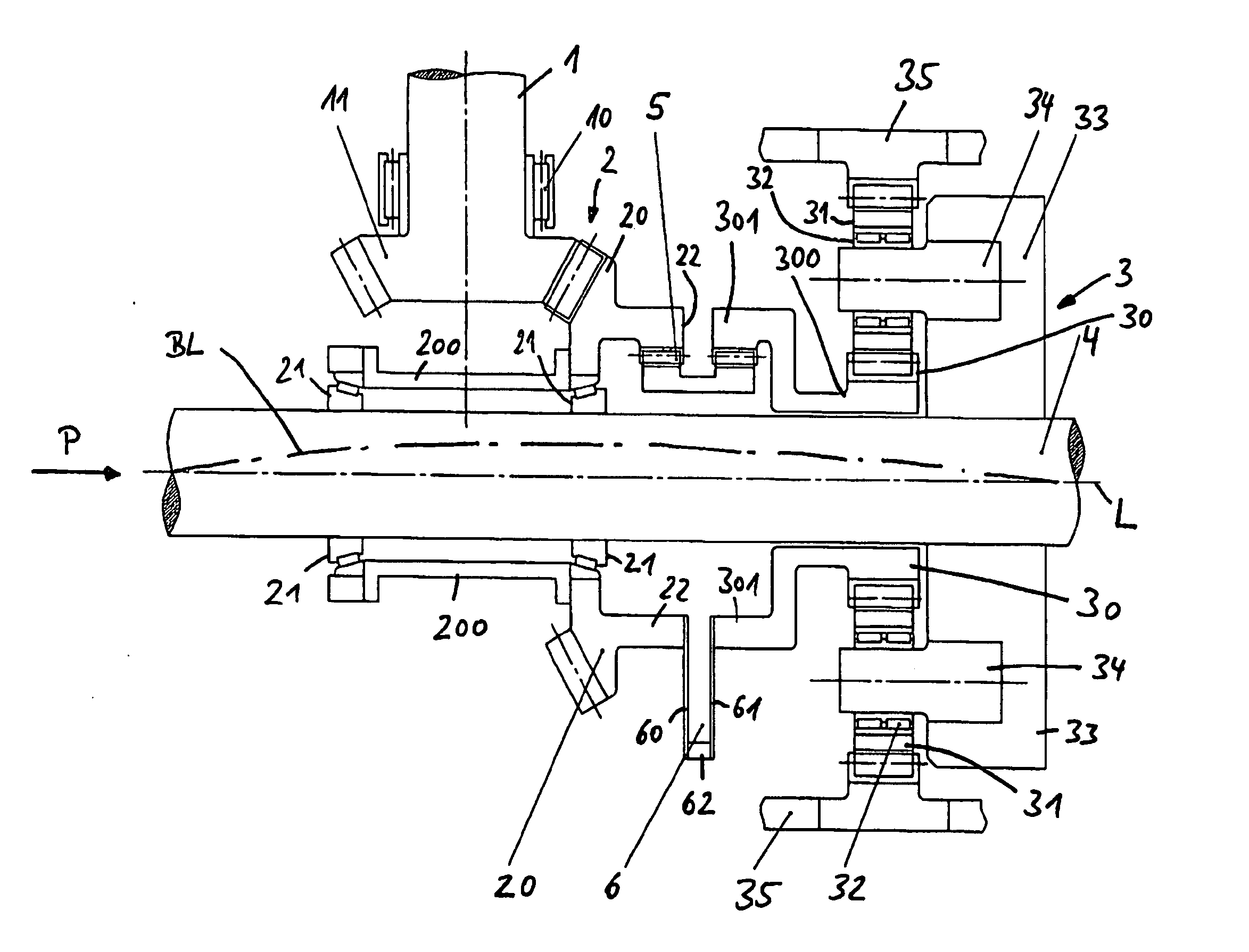
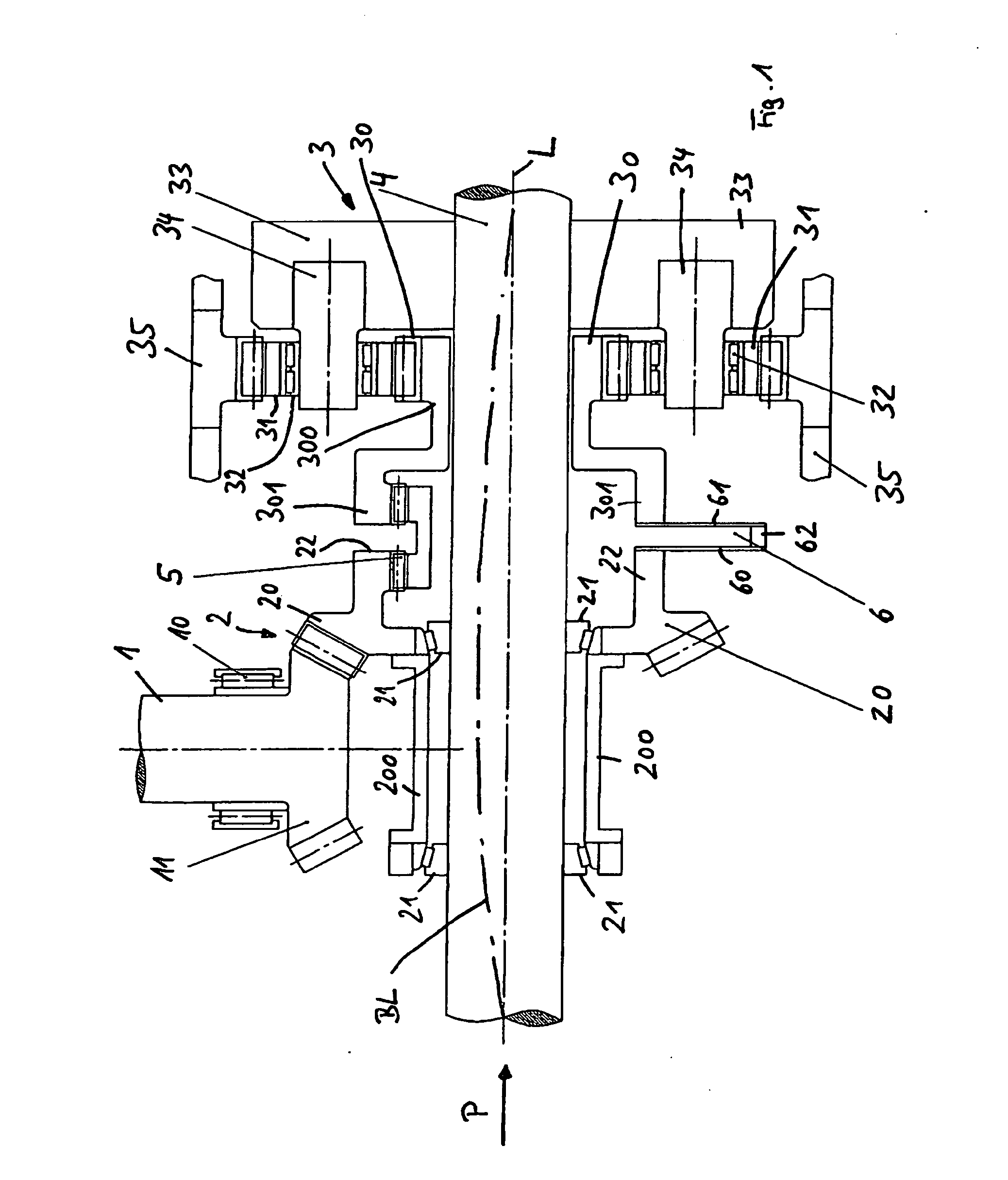
[0018]FIG. 1 shows the drive of a rudder propeller of an intrinsically known design in a schematic view showing only parts of an overall mechanism. The basic drive principle is known, for example, from German Patent Reference DE 28 43 459 A1, the entire description of which is included in this specification by reference.

[0019]Element reference numeral 1 indicates a vertically extending drive shaft 1 that extends down through or out of a hull and is set into rotation by a drive motor that is not shown in detail. The drive shaft 1 is supported by a pivot bearing 10 and at its end, has a pinion 11, which is a component of an angular drive 2 that is explained in greater detail below.

[0020]Element reference numeral 4 indicates a propeller shaft, which extends at right angles to the drive shaft 1 and, in a manner not shown in detail, supports a propeller for propulsion of the watercraft at its left end in the drawing of FIG. 1.

[0021]The drive motor, not shown, rotates the drive shaft 1 to...


PUM


Abstract

A rudder propeller including a drive shaft and a propeller shaft that can be driven by the drive shaft by an angular drive and a planetary gear that can be located on the propeller shaft and including a sun gear that is connected to the angular drive via a coupling, a fixed ring gear and planet gears that revolve between the sun gear and ring gear and that are mounted on a planet carrier. The planet carrier can be secured against torque to the propeller shaft and the coupling between the angular drive and the sun gear can be designed as a double cardanic, rotationally-fixed flexible coupling, in such a way that radial and angular displacements of the sun gear in relation to the angular drive can be compensated.

Description

BACKGROUND OF THE INVENTION[0001]1. Field of the Invention[0002]This invention relates to a rudder propeller with a drive shaft and a propeller shaft that can be driven by the drive shaft by an angular drive and a planetary gearing, the planetary gearing can be situated on the propeller shaft and include a sun gear connected to the angular gear by a coupling, a stationary ring gear, and planet gears that are mounted on a planet carrier and travel between the sun gear and the ring gear, and the planet carrier can be mounted to the propeller shaft in a torsionally rigid fashion.[0003]2. Discussion of Related Art[0004]Rudder propellers of the type mentioned above are known, for example, from German Patent Reference DE 28 43 459 A1. The rudder propeller is used to drive and steer a watercraft. The motor torque of a drive motor, which is usually situated inside the watercraft, is transmitted via a vertically extending drive shaft and an angular drive, which has a planetary gearing connec...

Claims


Application Information

Patent Timeline
Patent Type & Authority Applications(United States)
IPC IPC(8): B63H25/42
CPCB63H25/42B63H2023/0283B63H2023/342F16H1/48F16H37/084B63H5/125
Inventor HEER, MANFRED
Owner SCHOTTEL
Why Eureka
Try Eureka