Balanced-to-unbalanced transformer

a transformer and unbalance technology, applied in the direction of coils, waveguides, coupling devices, etc., can solve the problems of relatively expensive production of relativly bulky arrangements, unbalanced transformers constructed in printed circuit technology, etc., and achieve the effect of easy and inexpensive production in printed circuit technology

Inactive Publication Date: 2005-07-12
ROHDE & SCHWARZ GMBH & CO KG
View PDF8 Cites 20 Cited by
  • Summary
  • Abstract
  • Description
  • Claims
  • Application Information

AI Technical Summary

Benefits of technology

[0005]An object of the invention is to provide a balanced-to-unbalanced transformer for transmitting high power that can be produced easily and inexpensively in printed circuit technology and to specify a method of producing it.

Problems solved by technology

This results in relatively bulky arrangements that have to be relatively expensively produced manually and connected as separate components to the rest of the circuit.
The latter balanced-to-unbalanced transformers constructed in printed circuit technology are, however, normally only suitable for transmitting low high-frequency power.

Method used


Image

  • Balanced-to-unbalanced transformer
  • Balanced-to-unbalanced transformer

Examples


Embodiment Construction

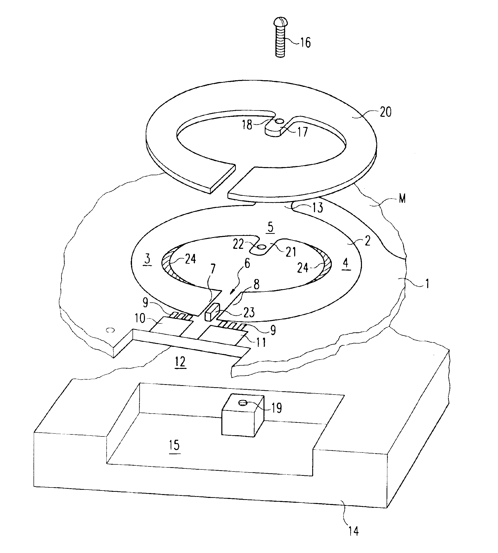
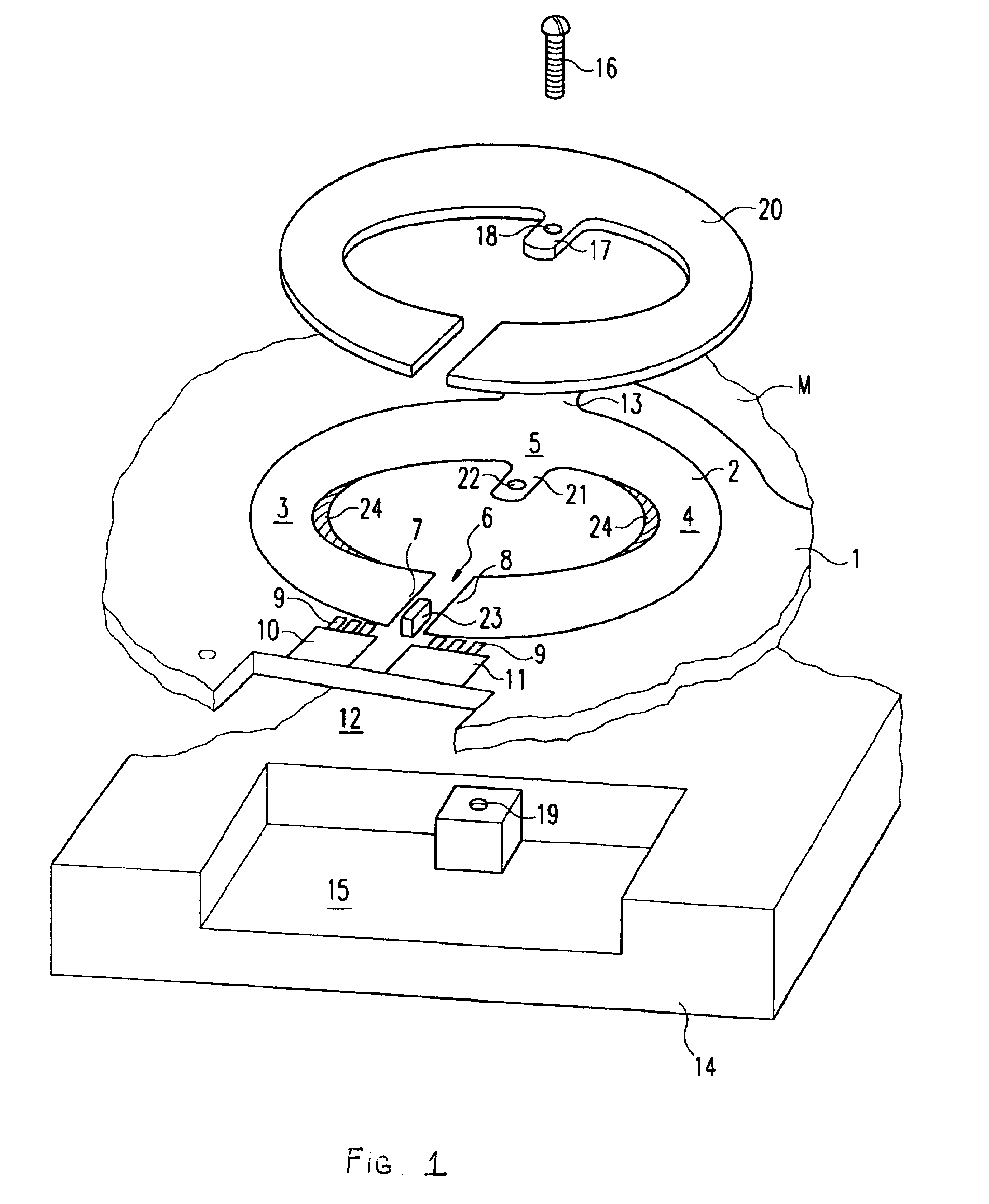
[0013]FIG. 1 illustrates a portion of a push-pull transistor power amplifier that is formed in printed circuit technology on a conductor board 1 shown in fragment form and whose balanced output is connected to a conductor loop 2, balanced with respect to ground M, of a balanced-to-unbalanced transformer. Said balanced conductor loop 2 has the shape of a circular ring pressed together from opposite sides and having two opposite C-shaped loop halves 3 and 4 that merge into one another integrally on the one side at 5 and form a slot 6 on the opposite side. Two opposite ends 7 and 8, forming the slot 6, of the C-shaped loop halves 3 and 4 form the balanced input of the balanced-to-unbalanced transformer, and they are electrically connected via transformer capacitors 9 to conductor tracks 10 and 11 with which the terminal lugs of the high-frequency power transistor, which is not shown and which is inserted in the rectangular recess 12, make contact.

[0014]The input circuit for the power t...


PUM

PropertyMeasurementUnit
frequencyaaaaaaaaaa
electricallyaaaaaaaaaa
areaaaaaaaaaaa

Abstract

A method relating to a balun for transmitting a high degree of high-frequency power where metal sheet element is soldered onto the loop conductor tract of the symmetrical circuit loop, the conductor track being configured as a printed circuit. The metal sheet element is leaked with a cooling element on the electrically cold mass point of the loop.

Description

[0001]This application is the national phase under 35 U.S.C. §371 of PCT International Application No. PCT / EP02 / 000146 which has an International filing date of Jan. 2, 2002, which designated the United States of America and which claims priority on Germany Patent Application number 101 05 696.6 filed Feb. 8, 2001, the entire contents of which are hereby incorporated herein by reference.FIELD OF THE INVENTION[0002]The invention relates to a balanced-to-unbalanced transformer (BALUN) for transmitting large high-frequency power, for example at the balanced output of a transistor power amplifier for coupling to an unbalanced output line.BACKGROUND OF THE INVENTION[0003]Balanced-to-unbalanced transformers for higher powers have hitherto been constructed in coaxial line technology. This results in relatively bulky arrangements that have to be relatively expensively produced manually and connected as separate components to the rest of the circuit.[0004]It is also already known to produce ...

Claims


Application Information

Patent Timeline
Patent Type & Authority Patents(United States)
IPC IPC(8): H01F27/28H01P5/10H01F27/08H01F27/22H03H7/42
CPCH01F27/2804H01P5/10H01F27/22H01F27/2876
Inventor KAEHS, BERNHARD
Owner ROHDE & SCHWARZ GMBH & CO KG
Why Eureka
Try Eureka