
Dosimeter, therapeutic apparatus, and computer program product for measuring radiation dosage to a subject during magnetic resonance imaging

Active Publication Date: 2013-08-22
KONINKLIJKE PHILIPS ELECTRONICS NV
View PDF3 Cites 21 Cited by
  • Summary
  • Abstract
  • Description
  • Claims
  • Application Information

AI Technical Summary

Benefits of technology

The patent is about a better way to see and measure the radiation dosage in combined MR and RT devices. This method allows for real-time measurement, without needing extra imaging time or extra dosage. The used substances are MR-compatible and safe. The method calculates a map that shows how much radiation is being absorbed in different parts of the body, based on the magnetic resonance data. This helps to estimate the type of tissue that the radiation is passing through.

Problems solved by technology

The accuracy and reproducibility of the setup in clinical routine are very important for correct patient position determination but this is difficult to accomplish with the first three techniques due to construction related insufficient mechanical reproducibility, inherent inaccuracies of spatial radiation localization via field-edge detection and unreliable / tedious registration of anatomical landmarks.
With EPIDs a dose and geometry verification is possible (non integrating dose measurement) but additional imaging radiation exposure (“monitor dose units”) is necessary for full treatment field imaging which increases the risk of cancer induction and is unfeasible for e.g. prostate imaging due to significant internal movement.
Also, extra imaging time is needed and the EPID devices are expensive.
But this integration of MR and RT devices results in spatial constraints (e.g. magnet surrounding patient in bore) which make the use of currently used radiation visualization devices (e.g. portal imaging with EPID, see above) difficult if not impossible.

Method used


Image

  • Dosimeter, therapeutic apparatus, and computer program product for measuring radiation dosage to a subject during magnetic resonance imaging
  • Dosimeter, therapeutic apparatus, and computer program product for measuring radiation dosage to a subject during magnetic resonance imaging
  • Dosimeter, therapeutic apparatus, and computer program product for measuring radiation dosage to a subject during magnetic resonance imaging

Examples


Embodiment Construction

[0072]Like numbered elements in these figures are either equivalent elements or perform the same function. Elements which have been discussed previously will not necessarily be discussed in later figures if the function is equivalent.

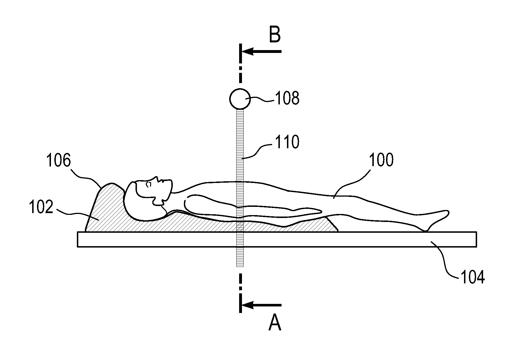
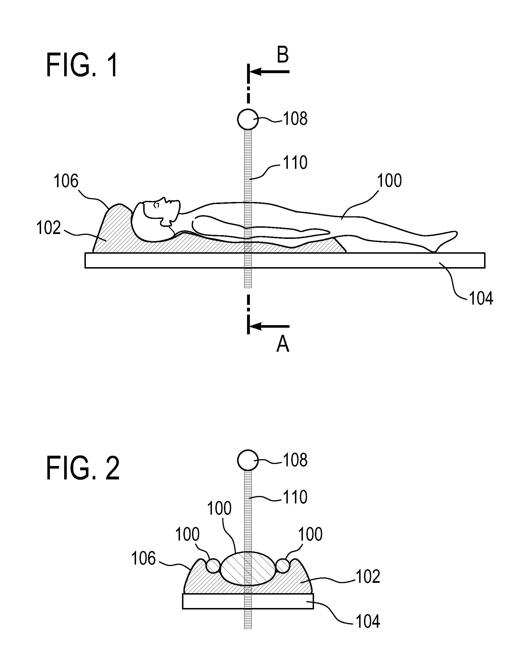
[0073]FIGS. 1 and 2 are used to illustrate the usage of a dosimeter according to an embodiment of the invention. FIG. 1 shows a side view of a subject reposing on a subject support 104. There is a dosimeter 102 between the subject and the subject support 104. The dosimeter 102 is in the form of a vacuum pillow or cushion for the subject 100 to repose upon. FIG. 2 is identical to that of FIG. 1 except in FIG. 2 a cross-section of the line marked AB in FIG. 1 is shown in FIG. 2. The dosimeter 102 is shown as having an outer thermal insulation layer 106 which thermally isolates the dosimeter 102 from the subject 100. Along the cross-section line AB there is a radiation source 108 which generates a beam of ionizing radiation 110. The ionizing radiation 110 ...


PUM


Abstract

A dosimeter (102, 300, 400, 500, 608, 610) for measuring radiation dosage to a subject (100, 604) during a magnetic resonance imaging guided radiation therapy session, the dosimeter comprising: an outer surface (106, 306, 308, 406, 408, 410, 412) adapted for receiving a surface (609, 611) of the subject, and discrete cells (302, 402, 512) each filled with a magnetic resonance radiation dosimeter.

Description

TECHNICAL FIELD[0001]The invention relates to radiation dosimetry, in particular to radiation dosimetry during magnetic resonance imaging.BACKGROUND OF THE INVENTION[0002]During radiotherapy (RT) treatments the radiation beam has to be focused on a well-defined target region and its dose has to be precisely controlled. To verify the accuracy of the radiotherapy treatment field relative to the patient, radiosensitive film, video vision systems, ion chambers and electronic portal imaging devices (EPIDs) are currently used for two-dimensional (real-time) monitoring of the applied dose. Additionally time-consuming regular quality assurance of (three-dimensional) radiation dose distribution has to be performed with specific phantoms.[0003]Some of the relevant characteristics of currently used radiation treatment field verification / dosimetry techniques are:[0004]Ion chamber (low resolution, slow, non-integrating dose measurement),[0005]Video chain (cumbersome, not geometrically accurate, ...

Claims


Application Information

Patent Timeline
IPC IPC(8): G01T1/02A61B5/00A61N5/10A61B5/055
CPCA61B5/055A61N5/1049A61N5/1071A61N2005/1055A61N2005/1072G01R33/4808A61B5/4836A61N5/1067A61N5/1077G01T1/02G01T1/04A61B5/0036
Inventor UHLEMANN, FALK
Owner KONINKLIJKE PHILIPS ELECTRONICS NV
Learn More