Modular Non-Linear Spring System

Active Publication Date: 2018-02-08
BARNES GROUP
View PDF5 Cites 2 Cited by
  • Summary
  • Abstract
  • Description
  • Claims
  • Application Information

AI Technical Summary

Benefits of technology

[0048]Another and/or alternative non-limiting object of the present disclosure is the provision of a modular non-linear spring system which can be e

Problems solved by technology

One disadvantage of such systems is that the brake pedal does not feel or behave like a brake pedal in a hydraulic braking system (e.g., in a non-linear, pr

Method used


Image

  • Modular Non-Linear Spring System
  • Modular Non-Linear Spring System
  • Modular Non-Linear Spring System

Examples


Example

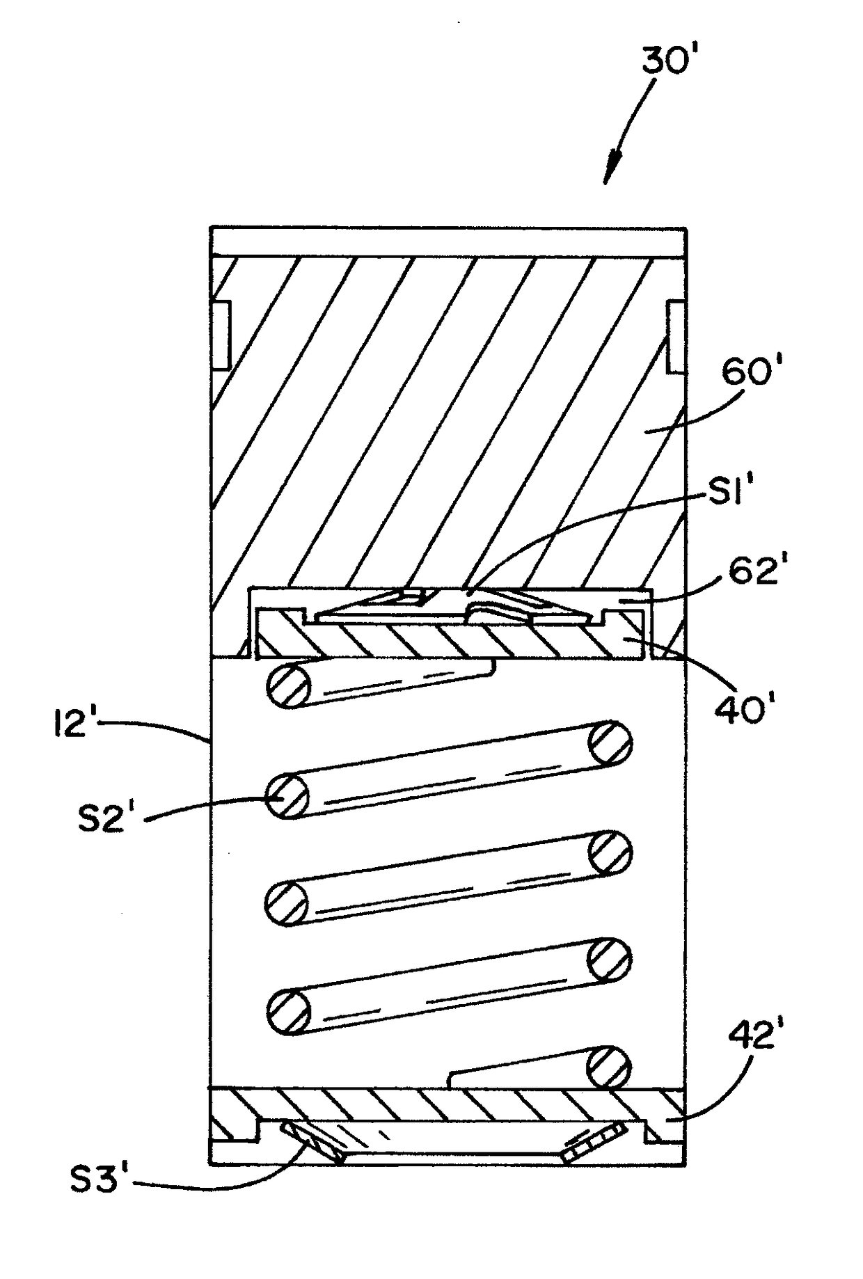
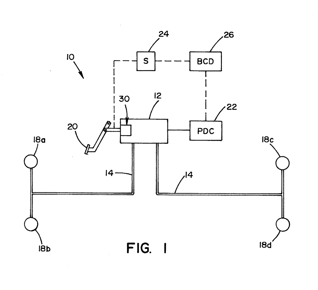
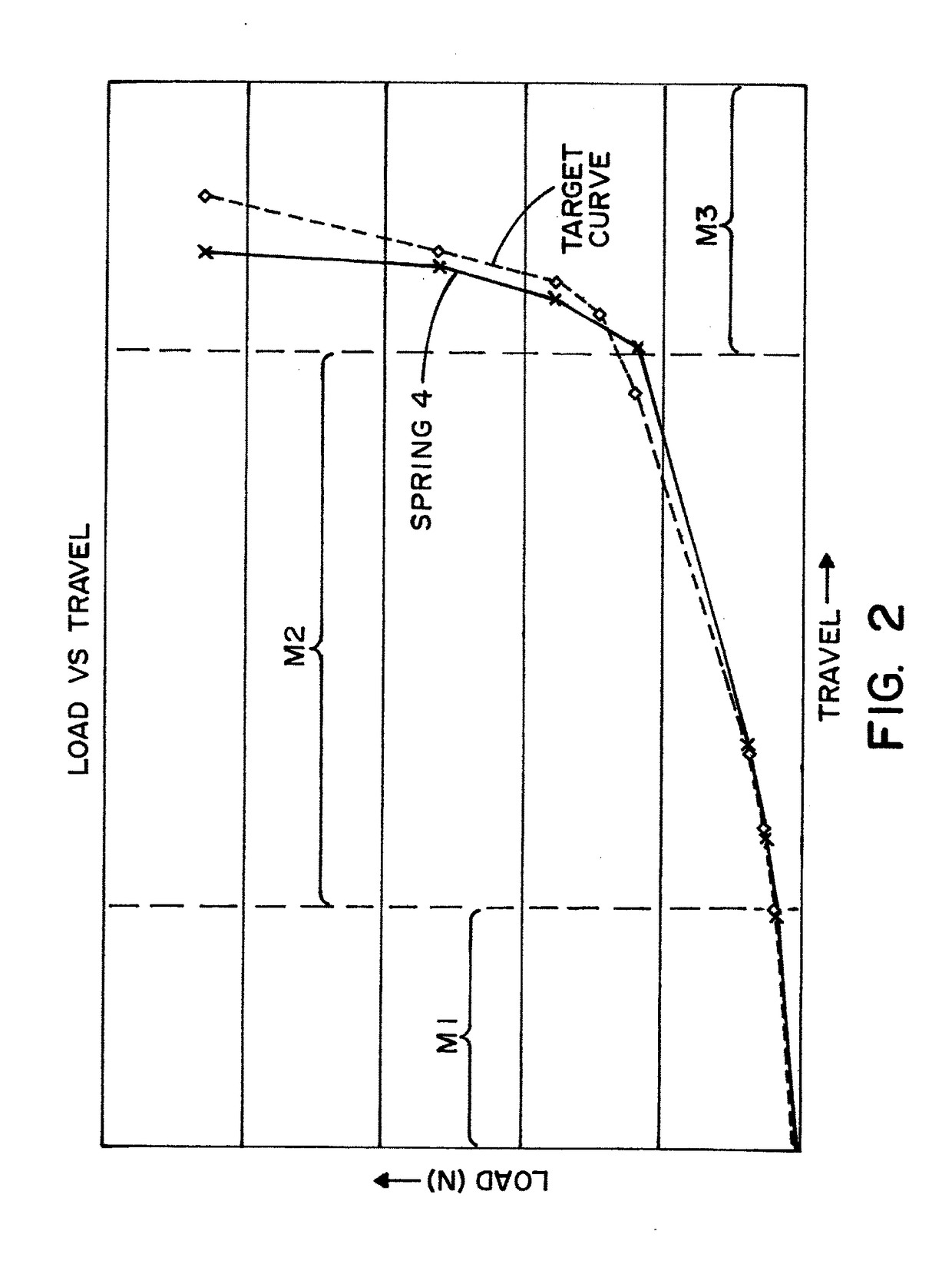
[0058]Referring now to the drawings, wherein the showings are for the purpose of illustrating non-limiting embodiments of the present disclosure only and not for the purpose of limiting the same, FIGS. 1-7 illustrate various non-limiting embodiments of an improved modular non-linear spring system which is capable of simulating traditional brake pedal feel.

[0059]In FIG. 1, an exemplary brake system 10 generally includes a master cylinder 12 coupled via hydraulic lines 14 to respective brake assemblies 18a-18d associated with respective wheels of a vehicle. The hydraulic lines 14 supply pressurized fluid from the master cylinder 12 to the brake assemblies 18a-18d during braking. The master cylinder 12 in the illustrated exemplary system generates the required pressure to actuate the brake assemblies 14a-14d, either via a foot pedal 20 or other pressure developing component 22 (e.g., mechanical or electric pump, actuator, etc.).

[0060]In a convention hydraulic brake system, all braking ...


PUM


Abstract

A modular non-linear spring system capable of simulating traditional brake pedal feel when incorporated into a hydraulic and/or electro-hydraulic vehicle braking system. The system can include a first spacer having a top surface and a bottom surface and an optional second spacer having a top surface and a bottom surface. In one arrangement, a first mechanical spring is in abutting engagement with the top surface of said first spacer, a second mechanical spring is in abutting engagement with the bottom surface of said first spacer and the top surface of said second spacer, and an optional third mechanical spring is in abutting engagement with the bottom surface of said second spacer. The springs are arranged to be progressively compressed using a brake pedal of the braking system.

Description

CROSS REFERENCE TO RELATED APPLICATIONS[0001]This application claims priority to and the benefit of the filing date of U.S. Provisional Patent Application Ser. No. 62 / 369,889, filed Aug. 2, 2016, which application is incorporated by reference in its entirety.[0002]The present disclosure relates to spring systems, particularly to spring systems having a non-linear force versus stroke profile, and more particularly to a non-linear spring system that can be used in a hydraulic and / or electro-hydraulic vehicle braking system, and which is capable of simulating traditional brake pedal feel.BACKGROUND OF THE INVENTION[0003]Motorized vehicles are generally slowed and / or stopped with hydraulic brake systems. A basic brake system generally includes a brake pedal, a master cylinder, brake fluid conduits arranged in two similar but separate brake circuits, and wheel brakes in each circuit. The driver of the vehicle operates the brake pedal which is connected to the master cylinder. When the br...

Claims


Application Information

Patent Timeline
IPC IPC(8): G05G5/03F16F3/02B60T11/16F16F3/04
CPCG05G5/03F16F3/04F16F3/02B60T11/165B60T7/06G05G2505/00F16F2228/066B60T7/042B60T8/4086B60T11/18
Inventor ADOLINE, JACKDAVIS, JOAQUINSICOTTE, JASON
Owner BARNES GROUP
Why Eureka
Try Eureka