
Spring part for retaining electric wires and terminal block comprising said spring part

a spring and electric wire technology, applied in the field of unidirectional spring parts, can solve the problems of reducing the possibility of adjusting the resilient force to be applied, reducing assembly complexity, and reducing the possibility of full electrical contact between wires and terminal blocks, so as to facilitate the adjustment of the resilient force, reduce the overall dimension, and reduce the effect of electrical load

Active Publication Date: 2010-11-16
MORSETTITALA
View PDF88 Cites 22 Cited by
  • Summary
  • Abstract
  • Description
  • Claims
  • Application Information

AI Technical Summary

Benefits of technology

"The technical problem addressed in this patent is to provide a small spring part that can withstand a high electrical load and can be easily adjusted for different types of wires. This part is easy and inexpensive to produce, can be used with different types of electrical connection devices, and can be easily operated by any user using standard tools."

Problems solved by technology

Although fulfilling their function, these known clamping means nevertheless have drawbacks which in the case of a screw-operated slider essentially are due to: the presence of the screw itself which tends to become loose over time, thus no longer ensuring the necessary clamping of the wire, and the fact that the said wire is clamped between two flat surfaces with complex forms which are difficult to produce, resulting in unevenness unable to ensure full electrical contact between wire and terminal block.
In the case of the spring, instead, the drawback is associated with the resilient force which must be imparted to the plate in order to ensure adequate clamping of the wire, which resilient force must be increased with an increase in the electrical loads and therefore the cross-section of the wire to be retained; in terminal blocks of the known type the resilient retaining means consist of parts constrained to supports by means of welds, rivets and the like, which complicate assembly and substantially reduce the possibility of adjusting the resilient force to be applied.
The technical problem which is posed, therefore, is to provide a spring part for retaining electric wires, in particular for use inside connection devices such as terminal blocks, connection boxes, wired-circuit switchboards and the like, which has small overall dimensions, but at the same time is able to withstand a high electrical load and which, in addition to facilitating assembly, also facilitates adjustment of the force to be imparted depending on the cross-section of the wire to be retained.

Method used


Image

  • Spring part for retaining electric wires and terminal block comprising said spring part
  • Spring part for retaining electric wires and terminal block comprising said spring part
  • Spring part for retaining electric wires and terminal block comprising said spring part

Examples


Embodiment Construction

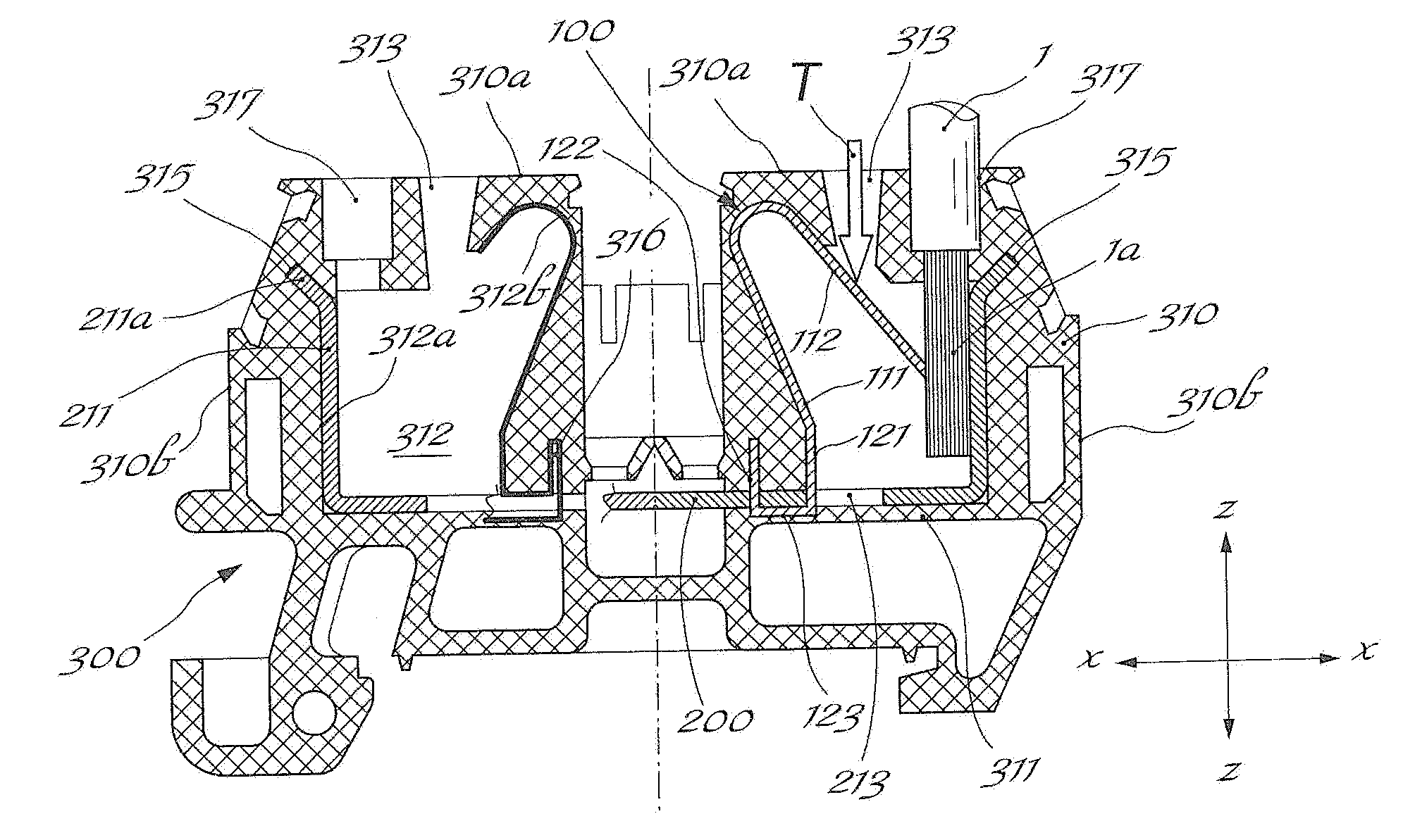
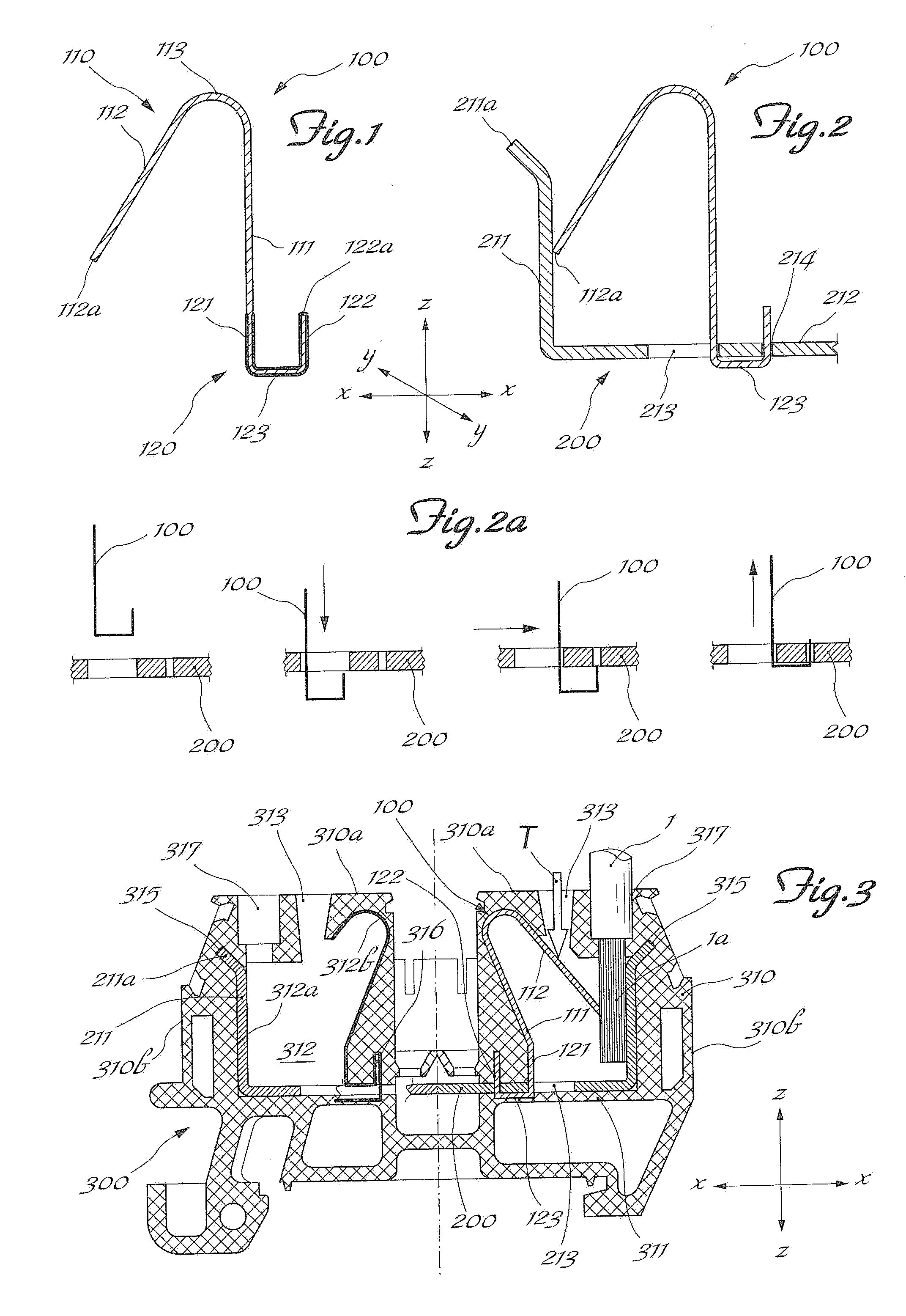
[0021]As shown in FIG. 1 and assuming solely for the sake of simplification of the description and without a limiting meaning a set of three reference axes in the longitudinal direction X-X, transverse direction Y-Y and vertical direction Z-Z, respectively, the spring part 100 for retaining electric wires 1 according to the present invention comprises a conducting body 110 substantially in the form of an overturned “U”, with one arm 111 substantially parallel to the vertical direction Z-Z and one arm112 forming an acute angle with the vertical arm 111 and having a free end 112a; the two arms 111,112 are connected together by a convex curved section 113 so as to produce the resilient reaction of the second or inclined arm 112 with respect to the vertical arm 111.

[0022]The vertical arm 111 can be joined to a U-shaped base 120 comprising: a first vertical arm 121 for connection to the vertical arm 111, a second vertical arm 122 with a free end 122a and a straight section 123 connecting...


PUM


Abstract

Spring part for retaining wires inside electric terminal blocks, comprising a conductor body substantially in the form of an overturned “U”, with a vertical arm substantially parallel to the vertical direction and a second arm forming an acute angle with the vertical arm and having a free end. The two arms being connected together by a convex curved section adapted to produce a resilient reaction of the second arm with respect to the vertical arm. The vertical arm can be joined to a U-shaped base formed from a first vertical arm, connected to the vertical arm of the conductor body, a second vertical arm having a free end and a longitudinal section connecting the two vertical arms. The U-shaped base being designed for stable engagement with a conducting part of the electric terminal block.

Description

DESCRIPTION[0001]1 Technical Field of the Invention[0002]The present invention relates to a unidirectional spring part for retaining electric wires inside electrical connection terminal blocks and a terminal block comprising the spring.[0003]2 Description of the Prior Art[0004]It is known, in the technical sector relating to electrical connection devices such as terminal strips, connection boxes and the like, to use terminal blocks designed to be mounted on corresponding supports and provide frontal access to the means—normally of the screw type—for retaining the electrical connection wires which form the electric circuit.[0005]It is also known that said means for retaining the end of the electric wire are normally designed with so-called sliders, movable in a direction perpendicular to the direction in which the wire is inserted, upon tightening a screw which causes retraction of the slider so as to grip the wire between the said slider and a counter plate extending parallel to the...

Claims


Application Information

Patent Timeline
Patent Type & Authority Patents(United States)
IPC IPC(8): H01R4/26
CPCH01R4/4827H01R9/2416H01R9/26H01R4/4821H01R4/485H01R4/4842
Inventor PIZZI, GIORDANO
Owner MORSETTITALA
Learn More