Toy carrying mechanism
- Summary
- Abstract
- Description
- Claims
- Application Information
AI Technical Summary
Benefits of technology
Problems solved by technology
Method used
Image
Examples
Example
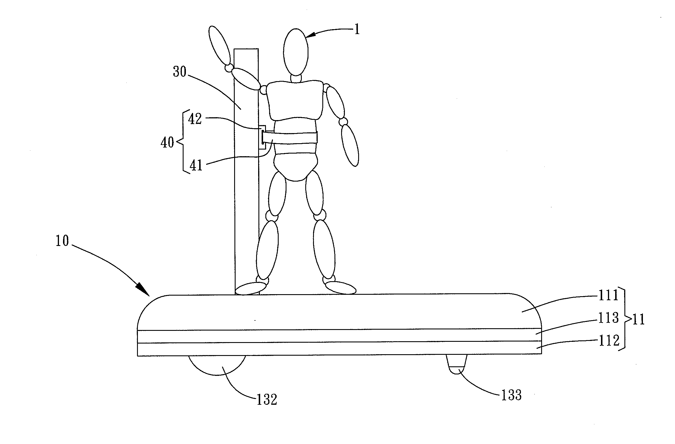
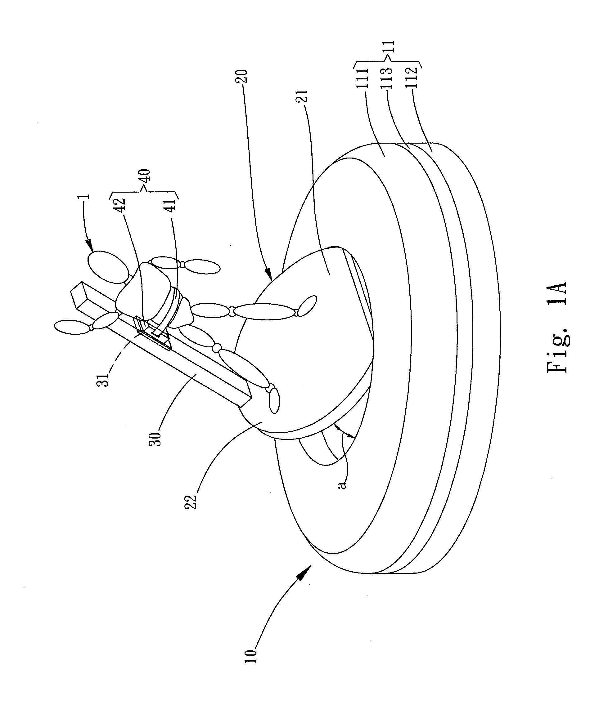
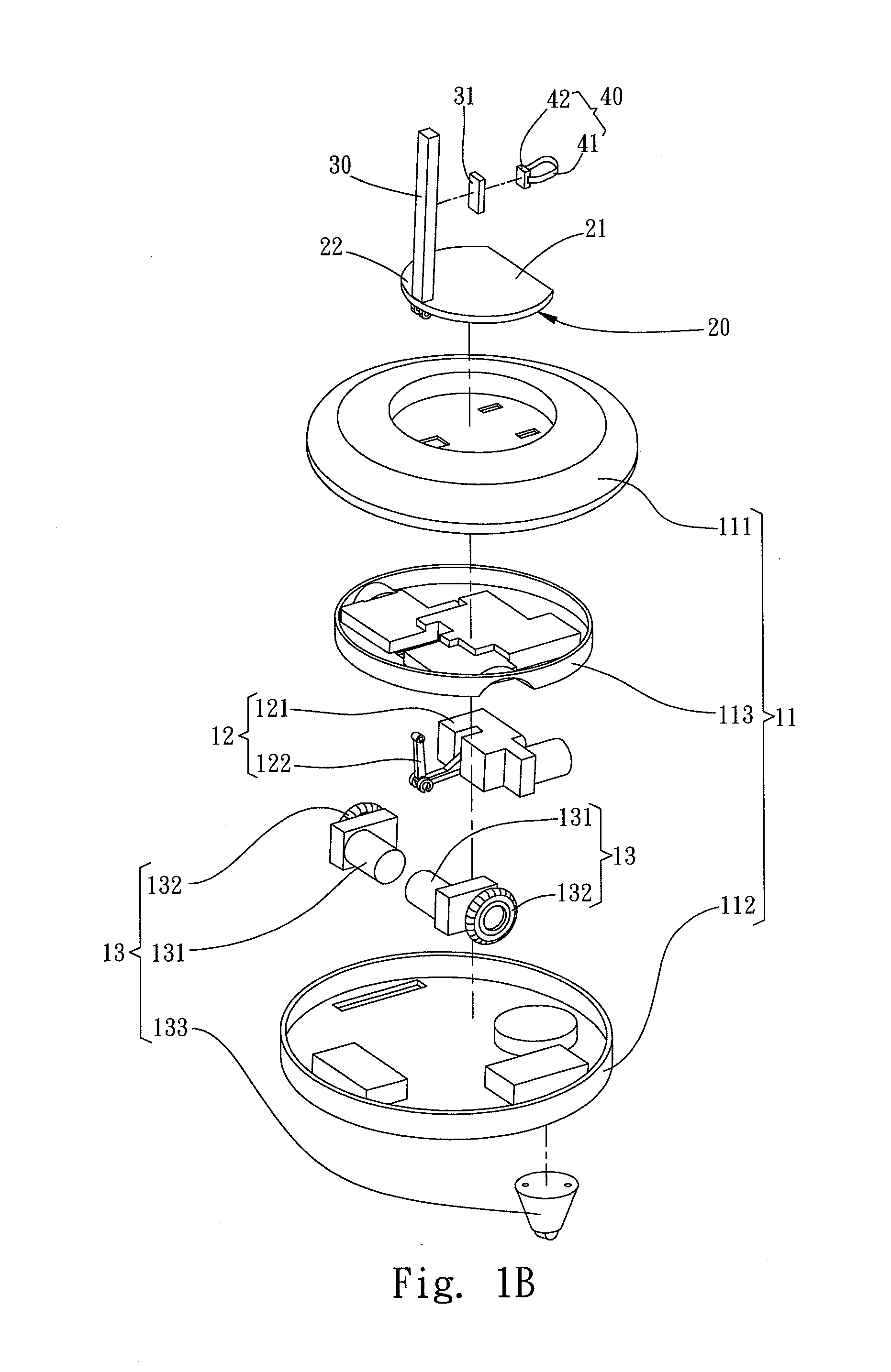
[0019]Please refer to FIGS. 1A and 1B for a first embodiment of the invention. The toy carrying mechanism according to the invention aims to carry a toy 1 and includes a carrying body 10, a movable deck 20, a support post 30 and a holding member 40.
[0020]The carrying body 10 includes a housing 11, a lift member 12 and a wheel set 13. The housing 11 includes an upper cap 111, a lower cap 112 coupled with the upper cap 111 and an assembly seat 113 located between the upper cap 111 and lower cap 112 and coupled therewith. The lift member 12 includes a transmission gear set 121 and a linkage bar 122. The transmission gear set 121 is fixedly located on the assembly seat 113. The linkage bar 122 has one end connected to the transmission gear set 121 and an opposite end run through the upper cap 111 to connect to the movable deck 20. The linkage bar 122 is driven by the transmission gear set 121 to generate movements in elevations. In this embodiment, the wheel set 13 includes a transmissi...
Example
[0024]Please refer to FIGS. 3A and 3B for a second embodiment of the invention, and FIG. 4 for the second embodiment coupled with a wiping member in a use condition. Compared with the first embodiment, the carrying body 10 also includes a speaker 50, an expansion module 60 and a wiping member 70. The speaker 50 is located on the lower cap 112 to broadcast a pre-recorded sound, or receive audio data signals from an external computer through a wireless transmission approach and broadcast the sound of the audio data signals.
[0025]The expansion module 60 includes a circuit board 61, a wireless transceiver 62 and a power supply slot 63. The circuit board 61 is located on the assembly seat 113. The wireless transceiver 62 is formed in a modular fashion and mounted onto the circuit board 61 to establish electric connection therewith so that the toy carrying mechanism can be controlled wirelessly through a remote controller or a computer via a wireless signal. The power supply slot 63 is lo...
Example
[0026]Please refer to FIGS. 5A and 5B for a third embodiment of the invention before and after coupling with an outer casing. Compared with the first embodiment, the third embodiment further includes an outer casing 114. The housing 11 has at least one latch hole 115 on the upper cap 111, and the outer casing 114 has a tenon corresponding to and latched in the latch hole 115 to couple with the upper cap 111 for mounting on the housing 11. The outer casing 114 can be formed in a desired profile to mate the carrying body 10, such as a motorcycle head grasped by the toy 1 formed in the shape of a human figure, or a tank turret coupled with a cannon to change the profile of the carrying body 10, thereby increasing diversity and improving entire appearance.
[0027]As a conclusion, the invention can move horizontally via the wheel set, and hold the toy on the movable deck through the support post and holding member to couple with the toy in use. The movable deck can be changed angularly and...
PUM
Abstract
Description
Claims
Application Information
- R&D Engineer
- R&D Manager
- IP Professional
- Industry Leading Data Capabilities
- Powerful AI technology
- Patent DNA Extraction
Browse by: Latest US Patents, China's latest patents, Technical Efficacy Thesaurus, Application Domain, Technology Topic.
© 2024 PatSnap. All rights reserved.Legal|Privacy policy|Modern Slavery Act Transparency Statement|Sitemap