Metallic Nanowire Ink Composition for a Substantially Transparent Conductor

a technology of substantially transparent conductors and nanowires, which is applied in the direction of inks, metal/alloy conductors, and conductors, can solve the problems of inability to transmit any appreciable amount of light in the visual spectrum or other important spectra, and the substantially opaque nature of the conductor

Inactive Publication Date: 2014-02-27
NTHDEGREE TECH WORLDWIDE
View PDF6 Cites 28 Cited by
  • Summary
  • Abstract
  • Description
  • Claims
  • Application Information

AI Technical Summary

Problems solved by technology

While such inks produce conductors (when cured) which are substantially conductive and have a comparatively low electrical impedance (or resistance), the resulting conductors are substantially opaque and do not allow the transmission of any appreciable amount of light in the visual spectrum or other important spectra, such as ultraviolet and infrared spectra.
Typical printable transparent conductors, while having reasonable optical transmissivity, unfortunately often have a comparatively high electrical impedance and low conductivity when cured, with resistances typically in the range of 800-1000 or more ohms per square (e.g., polyethylene-dioxithiophene).
In addition, many such transparent conductors (e.g., indium tin oxide (ITO)) require specialized deposition techniques and very high temperature processing to reduce impedance, or when cured in a resulting apparatus, tend to have limited, if any, flexibility.
Other printable transparent conductors are fragile when deposited, and may further require additional stabilization layers to hold the deposited but unstable metallic nanowires in place.
These types of printable transparent conductors have limited usefulness, however, as they cannot be readily utilized to provide electrical connections to devices, such as diodes, which are already placed on a substrate and which should not be subjected to potentially irreparably damaging treatments such as acid washes, etching, or compressive forces, for example.

Method used


Image

  • Metallic Nanowire Ink Composition for a Substantially Transparent Conductor
  • Metallic Nanowire Ink Composition for a Substantially Transparent Conductor
  • Metallic Nanowire Ink Composition for a Substantially Transparent Conductor

Examples


Embodiment Construction

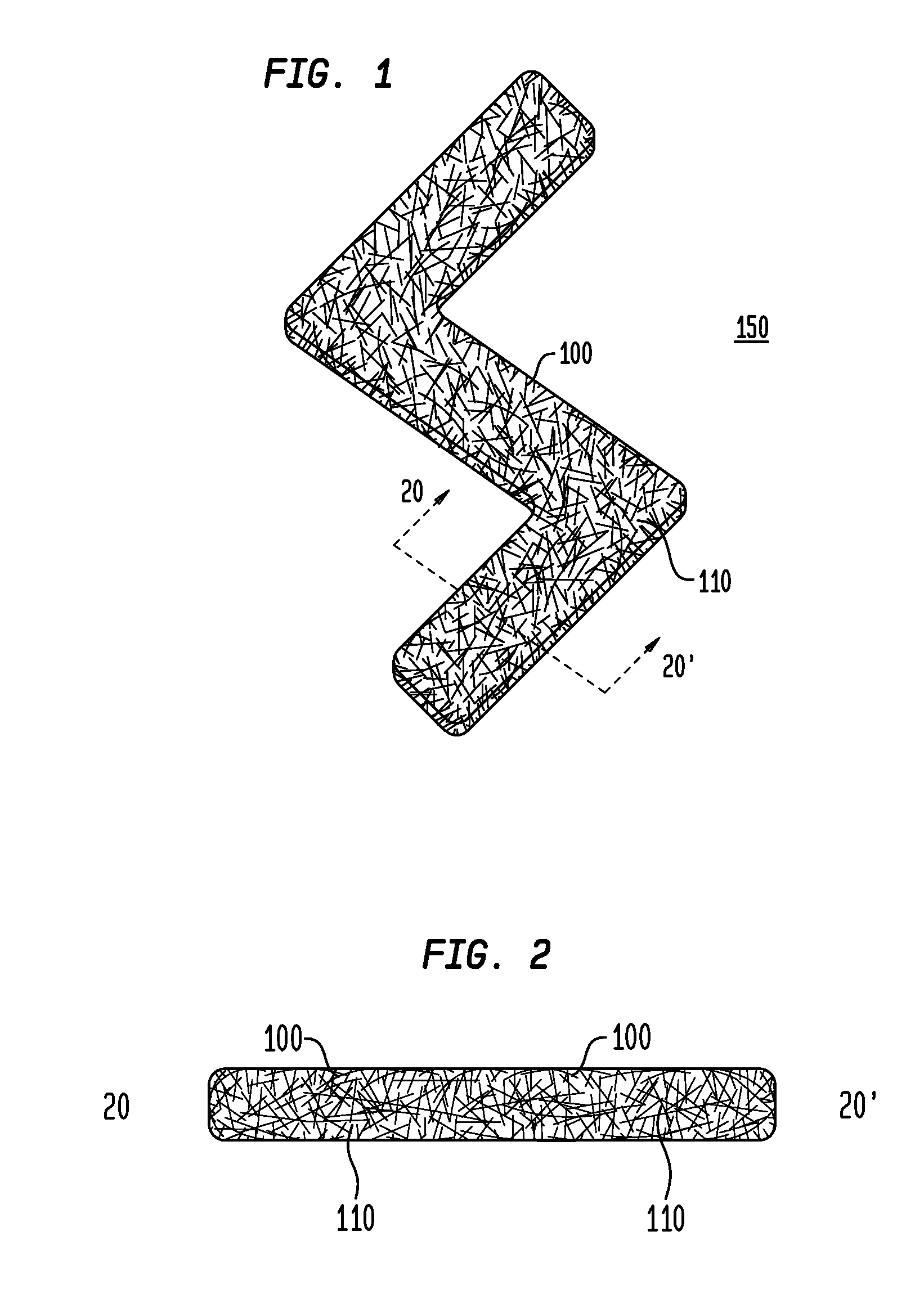
[0062]While the present invention is susceptible of embodiment in many different forms, there are shown in the drawings and will be described herein in detail specific exemplary embodiments thereof, with the understanding that the present disclosure is to be considered as an exemplification of the principles of the invention and is not intended to limit the invention to the specific embodiments illustrated. In this respect, before explaining at least one embodiment consistent with the present invention in detail, it is to be understood that the invention is not limited in its application to the details of construction and to the arrangements of components set forth above and below, illustrated in the drawings, or as described in the examples. Methods and apparatuses consistent with the present invention are capable of other embodiments and of being practiced and carried out in various ways. Also, it is to be understood that the phraseology and terminology employed herein, as well as...


PUM

PropertyMeasurementUnit
diametersaaaaaaaaaa
diametersaaaaaaaaaa
diametersaaaaaaaaaa

Abstract

An exemplary printable composition comprises a liquid or gel suspension of a plurality of metallic nanofibers or nanowires; a first solvent; and a viscosity modifier, resin, or binder. In various embodiments, an exemplary metallic nanowire ink which can be printed to produce a substantially transparent conductor comprises a plurality of metallic nanowires at least partially coated with a first polymer comprising polyvinyl pyrrolidone having a molecular weight less than about 50,000; one or more solvents such as 1-butanol, ethanol, 1-pentanol, n-methylpyrrolidone, cyclohexanone, cyclopentanone, 1-hexanol, acetic acid, cyclohexanol, and mixtures thereof; and a second polymer or polymeric precursor such as polyvinyl pyrrolidone or a polyimide, having a molecular weight greater than about 500,000.

Description

CROSS-REFERENCE TO RELATED APPLICATIONS[0001]This application as a continuation-in-part of and claims priority to U.S. patent application Ser. No. 13 / 360,999 filed on Jan. 30, 2012, which is a nonprovisional and conversion of and, under 35 U.S.C. Section 119, claims the benefit of and priority to U.S. Provisional Patent Application No. 61 / 447,160, filed Feb. 28, 2011, inventors Mark D. Lowenthal et al., both entitled “Metallic Nanofiber Ink, Substantially Transparent Conductor, and Fabrication Method”, which are commonly assigned herewith, incorporated by reference herein, and with priority claimed for all commonly disclosed subject matter. U.S. Pat. No. 8,454,859 issued Jun. 4, 2013 and commonly assigned herewith is also a continuation of U.S. patent application Ser. No. 13 / 360,999.FIELD OF THE INVENTION[0002]The present invention in general is related to conductive inks and polymers utilized to produce a substantially transparent conductor and, in particular, is related to a compo...

Claims


Application Information

Patent Timeline
Patent Type & Authority Applications(United States)
IPC IPC(8): H01B1/22
CPCH01B1/22B82Y30/00C09D11/033C09D11/106C09D11/52H01L31/022466H01L31/1884Y02E10/50
Inventor LOWENTHAL, MARK DAVIDLEWANDOWSKI, MARKBALDRIDGE, JEFFREYZHENG, LIXINCHESLER, DAVID MICHAEL
Owner NTHDEGREE TECH WORLDWIDE
Why Eureka
Try Eureka