Electrical connector assembled component

Active Publication Date: 2014-03-06
HIROSE ELECTRIC GROUP
View PDF2 Cites 13 Cited by
  • Summary
  • Abstract
  • Description
  • Claims
  • Application Information

AI Technical Summary

Benefits of technology

[0024]As described above, in the electrical connector assembled component a flexible section equipped with a locking section is formed by a slit groove formed in the first housing of the first connector, and an engaging step-like section is formed as a locked section in the second housing of the second connector. Therefore, there is no need to provide a flexible section in the second connector as in the conventional connector of Patent Reference. Furthermore, since it is configured to unlock by guidin

Problems solved by technology

However, according to the conventional electrical connector assembled component disclosed in Patent Reference, the connector has to have a complicated configuration, which results in poor strength.
Moreover, there is another issue of high manufacturing cost due to the dies and complicated molding step thereof.
Separately having the arc-shaped flexible arm to release the locking, which exten

Method used


Image

  • Electrical connector assembled component
  • Electrical connector assembled component
  • Electrical connector assembled component

Examples


Example

[0032]Hereunder, referring to the accompanying drawings, embodiments of the invention will be described.

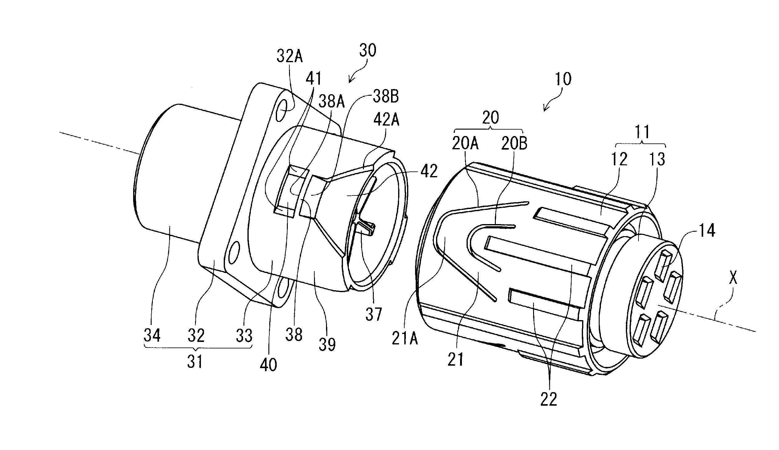
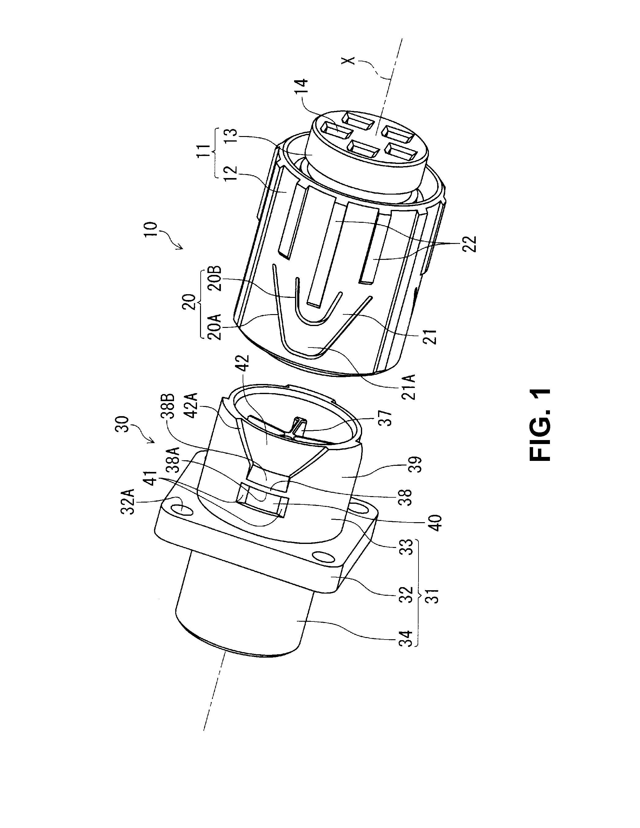
[0033]According to the embodiment, a first connector 10 formed as a plug connector and a second connector 30 formed as a receptacle connector compose a connector assembled component, being fitted to each other as shown in perspective view of FIG. 1 and a sectional view of FIG. 3.

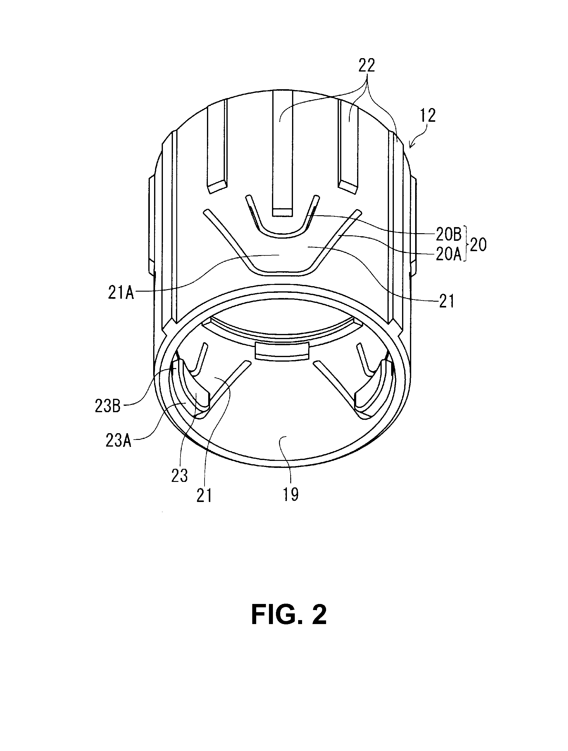
[0034]According to the embodiment, the first connector 10 includes a housing 11 made of an electrically insulating material (hereinafter the housing of the first connector 10 is referred to as a “first housing” and a housing of the second housing 30 is referred to as a “second housing” for clarification between housings of the first connector 10 and the second connector 30). The housing 11 is composed of a sleeve-like outer housing 12 and a column-like inner housing 13 provided inside the outer housing 12. The outer housing 12 is attached so as to be capable of rotating relative to the inner housing 13 in ...


PUM


Abstract

An electrical connector assembled component includes a first connector and a second connector, which can fit and separate to/from each other along an axis. The first connector includes a first housing, and the second connector has a second housing. The first housing has a flexible section formed with a slit groove that penetrates in the radial direction in the fitting tube, and the flexible section has a locking section that protrudes inward in the radial direction from the cylindrical fitting surface. The second housing includes a locked section, in which there is formed an engaging step-like section that contacts with the locking section in the fitting process so as to elastically flex and displace the locking section to allow movement in the fitting direction to the locking position and locks with the locking section in the connector-removal direction.

Description

BACKGROUND OF THE INVENTION AND RELATED ART STATEMENT[0001]The present invention relates to an electrical connector assembled component. Especially, the present invention relates to an electrical connector assembled component having a lock mechanism to lock upon connector fitting and to release the lock mechanism.[0002]Patent Reference has disclosed a conventional electrical connector assembled component. According to the electrical connector assembled component disclosed in Patent Reference, a first connector and a second connector, each of which has a fitting tube section, fit and lock to each other in an axial direction. Once the first connector and the second connector rotate along the circumferential directions relative to each other, the locking is released.[0003]Patent Reference: Japanese Patent Publication No. 4,711,808[0004]According to the electrical connector assembled component disclosed in Patent Reference, on an inner circumferential surface of the fitting tube section...

Claims


Application Information

Patent Timeline
IPC IPC(8): H01R13/627
CPCH01R13/625H01R13/6271
Inventor YAMADA, YOSHIHISA
Owner HIROSE ELECTRIC GROUP
Why Eureka
Try Eureka