Hinged row crop auger conveyor

a conveyor and row crop technology, applied in packaging, agriculture tools and machines, agriculture, etc., can solve the problems of difficult to conform to the surface of the field, inability to properly harvest the crops planted on undulating terrain,

Active Publication Date: 2014-03-20
DEERE & CO
View PDF8 Cites 21 Cited by
  • Summary
  • Abstract
  • Description
  • Claims
  • Application Information

AI Technical Summary

Problems solved by technology

One problem with these larger harvesting heads is their inability to properly harvest crops planted on undulati

Method used


Image

  • Hinged row crop auger conveyor
  • Hinged row crop auger conveyor
  • Hinged row crop auger conveyor

Examples


Embodiment Construction

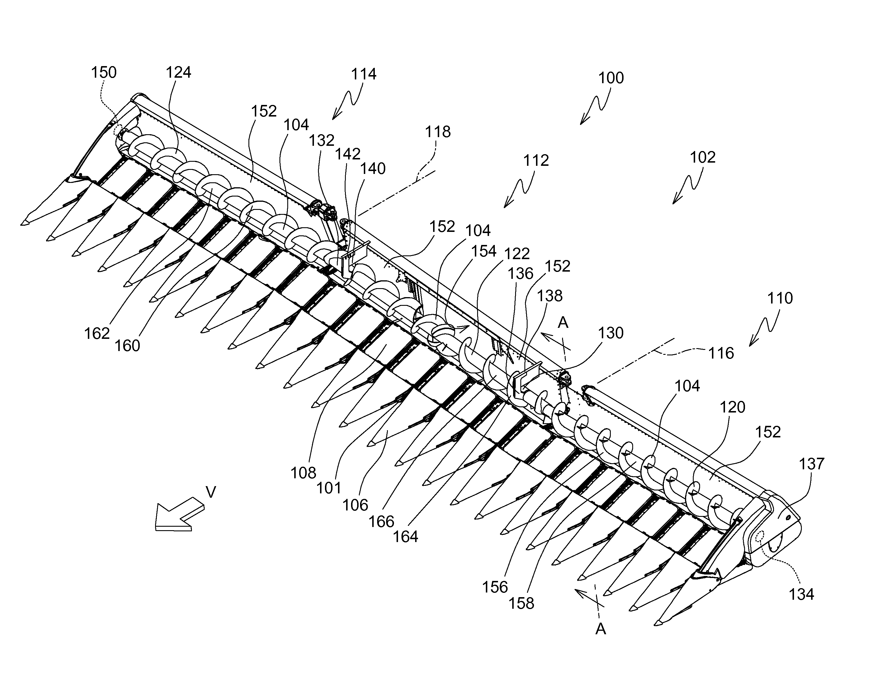
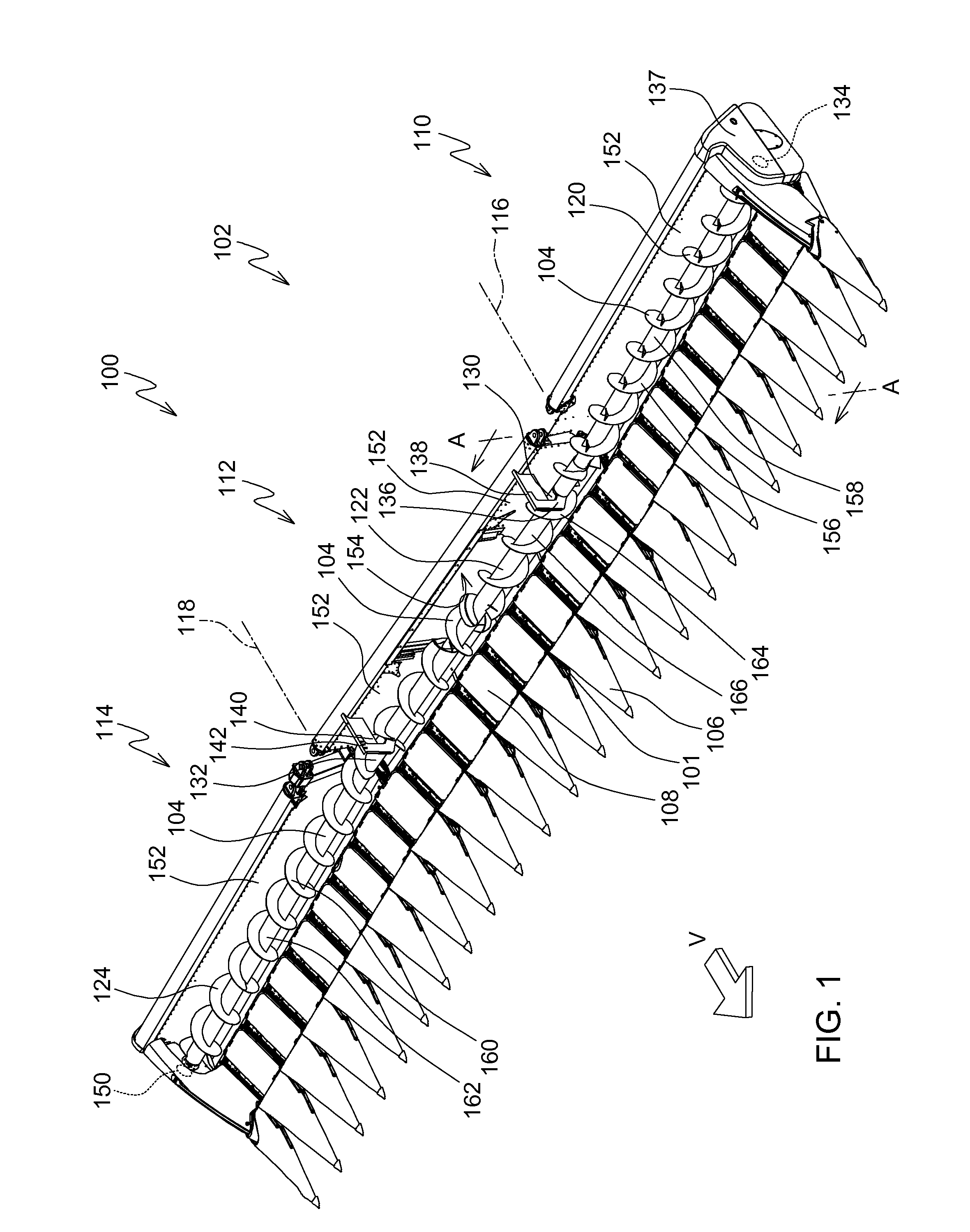
[0039]Referring to FIG. 1, a corn head 100 is shown having a frame 102 that extends laterally and generally perpendicular to the direction of travel “V” of the corn head as it travels through the field harvesting crop.

[0040]Corn head 100 further comprises a conveyor 104 that extends substantially the entire longitudinal extent of the corn head 100 and generally perpendicular to the direction of travel of travel “V”.

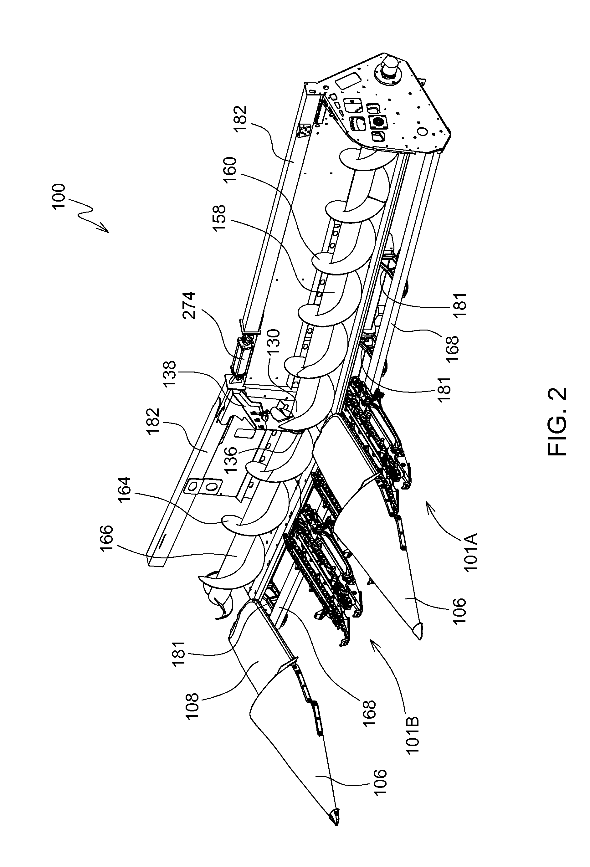
[0041]Corn head 100 further comprises a plurality of row units 101 fixed to frame 102 and extending forward therefrom. In FIG. 1, these row units are covered by corresponding points 106 and covers 108 disposed behind the points 106 that serve to divide the crop into individual rows and feed the crop into the gap between the arms 170 of adjacent row units 101. These row units 101 are seen in greater detail in FIGS. 2-7.

[0042]Frame 102 comprises three laterally extending frame sections 110, 112, 114 that are pivotally coupled together to permit the three frame sections to p...


PUM


Abstract

An auger conveyor (104) is provided for a row crop harvesting head (100) that has a hinged frame (102). The auger conveyor (104) has a first section (122) that is coupled to a second section (120, 124) with a universal joint (130).

Description

RELATED APPLICATIONS[0001]This application is related to and claims priority from U.S. Provisional Patent Application 61 / 703,740, which was filed Sep. 20, 2012. This application is related to U.S. Provisional Patent Applications Nos. 61 / 703,752 and 61 / 703,745 which were also filed on Sep. 20, 2012.FIELD OF THE INVENTION[0002]This invention relates to row crop harvesting heads. More particularly, it relates to auger conveyors for row crop harvesting headsBACKGROUND OF THE INVENTION[0003]Row crop harvesting heads such as corn heads are being manufactured in ever increasing widths. Combine harvesters are made larger and more powerful and capable of carrying larger harvesting heads.[0004]One problem with these larger harvesting heads is their inability to properly harvest crops planted on undulating terrain. The longer harvesting heads become, the harder it is for them to conform to the surface of the field.[0005]What is needed, therefore, is an improved row crop harvesting head for a c...

Claims


Application Information

Patent Timeline
IPC IPC(8): A01D61/00A01D45/02
CPCA01D45/021A01D61/002A01D61/004
Inventor HEIM, DANIEL M.VANDEVEN, MICHAEL L.
Owner DEERE & CO
Why Eureka
Try Eureka