
High Density Perforating Gun System Producing Reduced Debris

a perforating gun and high density technology, applied in the direction of fluid removal, explosive charges, wellbore/well accessories, etc., can solve the problems of large capital investment required for commercial development of hydrocarbon fields, unavoidable interstitial space between neighboring charges, and placement of perforation charges, etc., to achieve effective perforation and reduce the amount of debris resulting from detonation

Inactive Publication Date: 2014-03-27
OWEN OIL TOOLS
View PDF7 Cites 2 Cited by
  • Summary
  • Abstract
  • Description
  • Claims
  • Application Information

AI Technical Summary

Benefits of technology

This patent describes a device that detonates to create holes in structures. The device is made up of a high explosive, a liner, and an outer cover. When the device detonates, these components are largely destroyed, resulting in less debris compared to other devices.

Problems solved by technology

Commercial development of hydrocarbon fields requires significant amounts of capital.
This may be difficult, however, because there are limitations relating to placement of the charges used for perforation.
When packing the charges in an adjoining manner in the charge tube, interstitial spaces are unavoidably left between the neighboring charges as a result their shape.
This packing of the charges results in significant “dead spaces,” that is, areas from which no perforating product, i.e., no jets, is / are provided, between the charges, and limits the density with which the charges can be packed.
This debris is undesirable, both because it must be removed by wireline or by other means in a secondary operation, and because it may clog the perforations that are formed by the perforation operation, thereby making the perforations less effective and sometimes necessitating repeat perforation operations.
The Chawla et al. invention thus suffers from problems relating to both “dead space” and debris creation.

Method used


Image

  • High Density Perforating Gun System Producing Reduced Debris
  • High Density Perforating Gun System Producing Reduced Debris
  • High Density Perforating Gun System Producing Reduced Debris

Examples


Embodiment Construction

[0030]The present disclosure relates to devices and methods for perforating wellbores. The present disclosure is susceptible to embodiments of different forms. These are shown in the drawings, and herein will be described in detail, specific embodiments of the present disclosure with the understanding that the present disclosure is to be considered an exemplification of the principles of the disclosure, and is not intended to limit the disclosure to that illustrated and described herein.

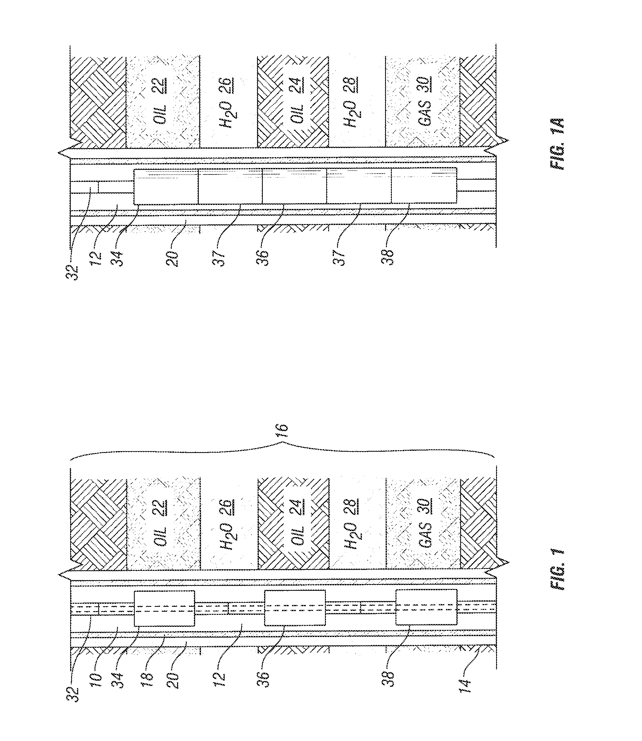
[0031]FIG. 1 illustrates an exemplary perforation system 10 that is configured in accordance with one embodiment of the present disclosure. The perforation system 10 is disposed within a wellbore 12 that has been drilled through the earth 14 and a hydrocarbon-bearing formation 16. Portions of the wellbore 12 are cased by a steel casing 18 that is secured within the open wellbore hole by cement 20.

[0032]The hydrocarbon-bearing formation 16 contains two oil-bearing strata 22, 24, which are separated by...


PUM


Abstract

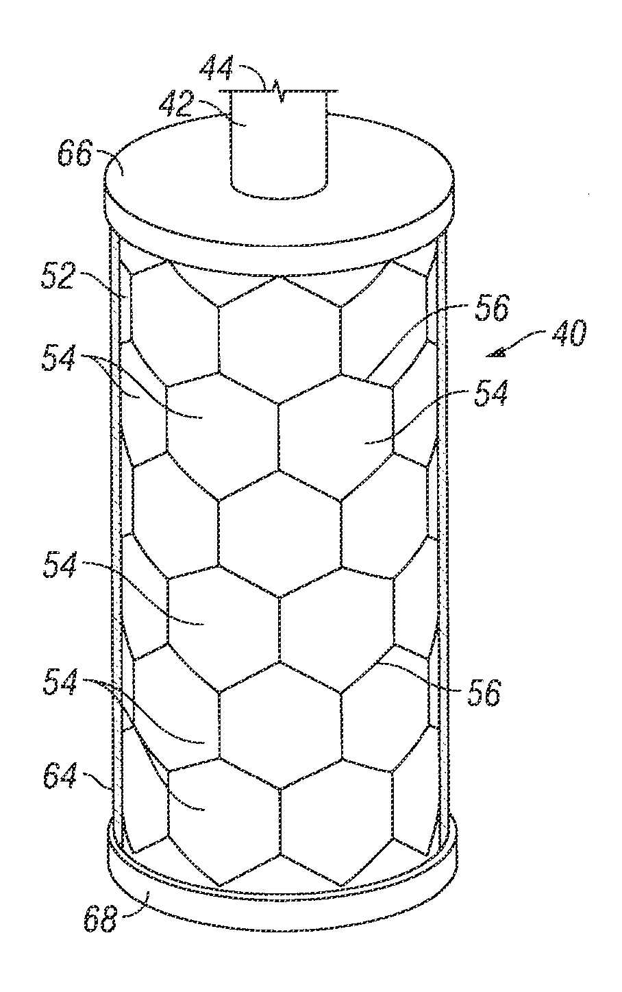
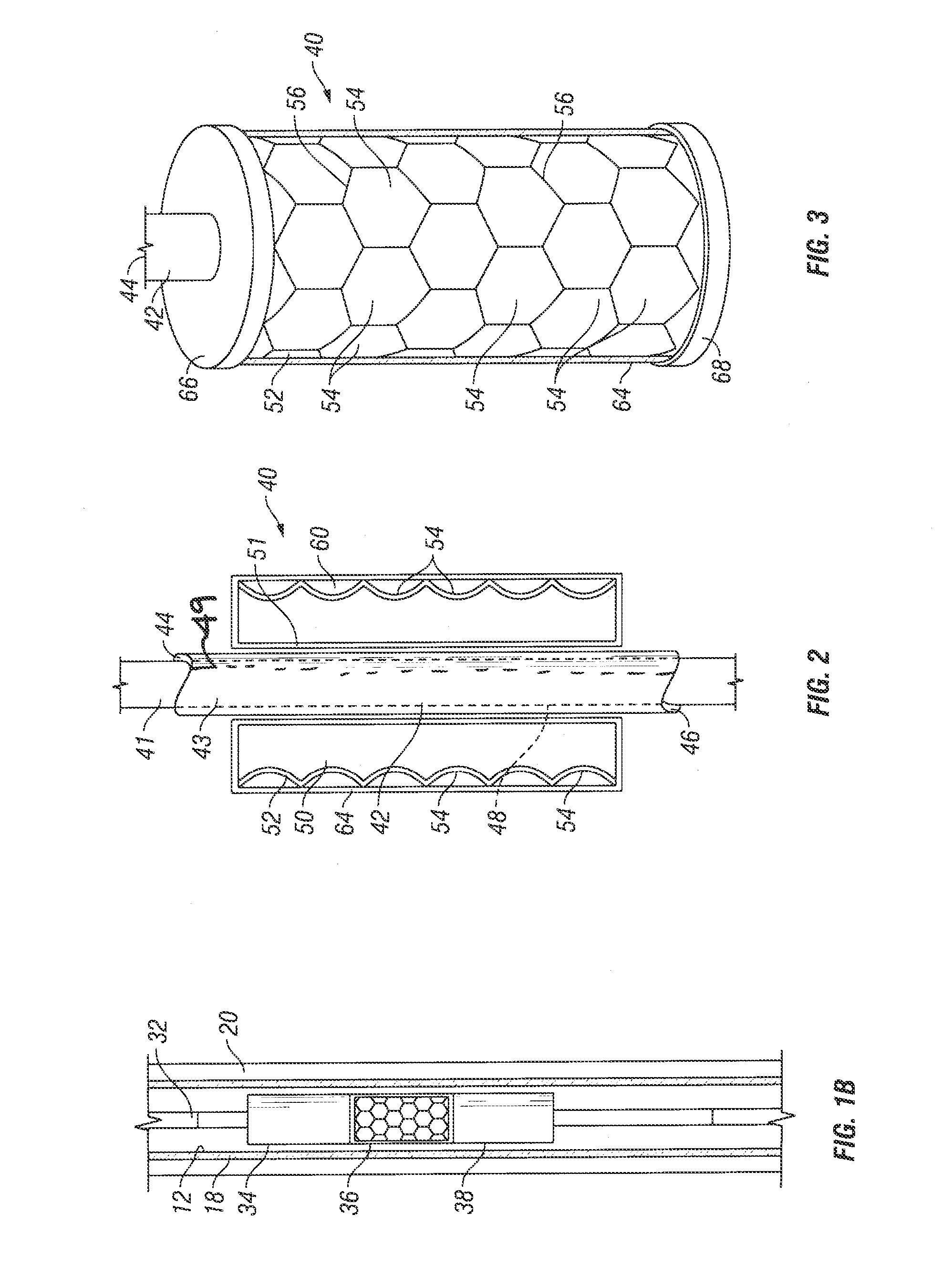
A perforating system has a perforating module comprising a unitary body of explosive. The explosive is contained within a non-explosive casing, or liner, having formed indentations and a cover thereover. The indentations, which will transform into explosively formed penetrators (EFP's) upon detonation, have a perimeter shape that allows for improved packing density, e.g., a hexagonal perimeter, which results in relatively little “dead space” wherein no perforating penetrators are generated. In operation, the module provides a relatively dense shot pattern and substantially reduced amount of post-detonation debris that could clog the perforations and / or require remedial clean-up or repeat perforation.

Description

CROSS-REFERENCES TO RELATED APPLICATIONS[0001]This application is a continuation of and claims priority from U.S. patent application Ser. No. 12 / 541,827 filed Aug. 14, 2009, which in turn is a continuation-in-part of and claims priority from U.S. patent application Ser. No. 11 / 405,148, filed on Apr. 17, 2006, all of which are incorporated herein by reference in their entirety.BACKGROUND OF THE DISCLOSURE[0002]1. Field of the Disclosure[0003]The disclosure relates generally to the design of perforating tools for use in creating perforations in wellbores to improve the flow of fluids from the wellbore.[0004]2. Description of the Related Art[0005]Commercial development of hydrocarbon fields requires significant amounts of capital. Therefore, before field development begins, operators desire to have as much information as possible in order to evaluate the reservoir for commercial viability. Such information may be acquired at the seismic exploration phase, during well construction, prio...

Claims


Application Information

Patent Timeline
Patent Type & Authority Applications(United States)
IPC IPC(8): E21B43/117
CPCE21B43/117F42B1/028F42D3/00
Inventor PRATT, DAN W.CHAWLA, MANMOHAN SINGH
Owner OWEN OIL TOOLS
Learn More