Intermodal container having a resilient liner

a resilient liner and intermodal container technology, applied in the field of modification of intermodal containers, can solve the problems of inefficient supply chain logistics, increased cost for individual fracing companies and well operators, and considerable amount of modification inside the intermodal container

Inactive Publication Date: 2014-04-10
SANDCAN INC
View PDF4 Cites 94 Cited by
  • Summary
  • Abstract
  • Description
  • Claims
  • Application Information

AI Technical Summary

Benefits of technology

[0017]Located between the upper hatch and the lower hatch, and securely attached on each end thereto, is a resilient liner that extends vertically from the upper hatch to the lower hatch. When the upper hatch is open and proppant such as sand inserted therein, if the lower hatch is closed, the proppant will begin to accumulate inside the resilient liner. The weight of the column of proppant will cause the resilient liner to extend outward in a balloon-like fashion. Continued insertion of the proppant (i.e., sand) through the upper hatch into the resilient liner will cause the resilient liner to expand outward until essentially the entire intermodal container is filled with the proppant inside the resilient liner. The only vacant space will be around the outer top portion of the intermodal container as determined by the angle of repose of the proppant. Thereafter, the intermodal container filled with the proppant can be shipped to the desired location for unloading.

Problems solved by technology

If the proppant comes from other countries, it is typically delivered to the United States by ship and is handled at multiple locations in multiple ways that is very inefficient for supply chain logistics.
The more the fracing proppant is handled, the more expensive it is to the individual fracing company as well as the well operator.
However, a considerable amount of modification is necessary inside the intermodal container to get all of the proppant in and out of the intermodal container when loading and emptying.

Method used


Image

  • Intermodal container having a resilient liner
  • Intermodal container having a resilient liner
  • Intermodal container having a resilient liner

Examples


Embodiment Construction

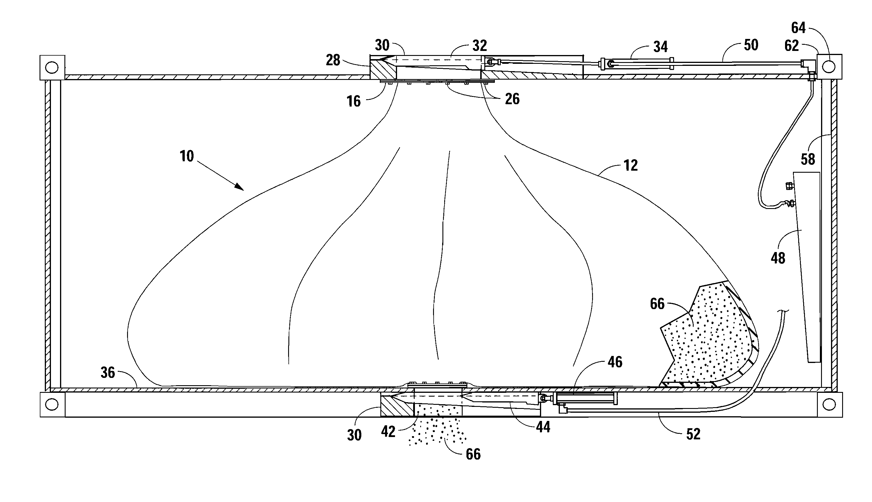
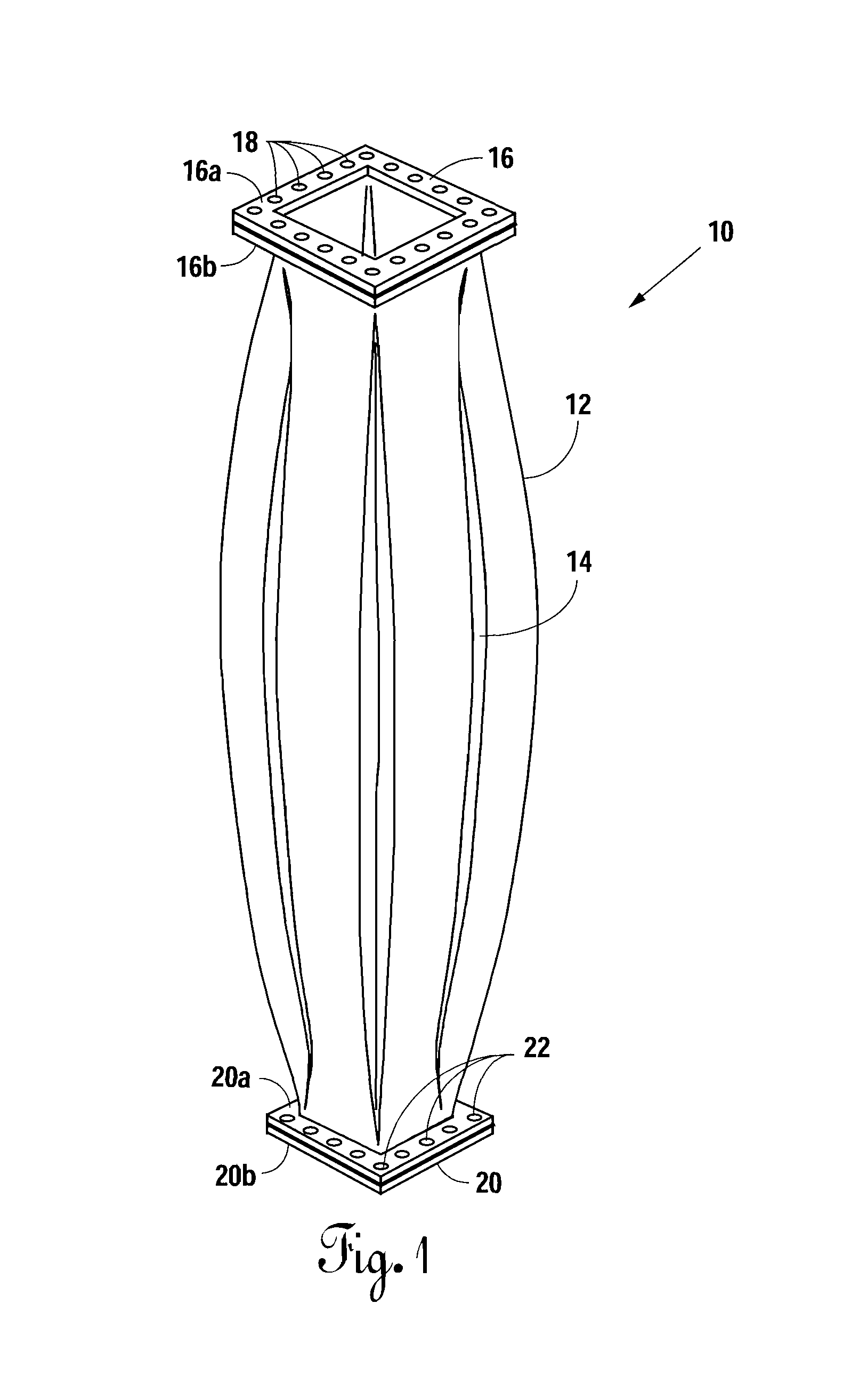
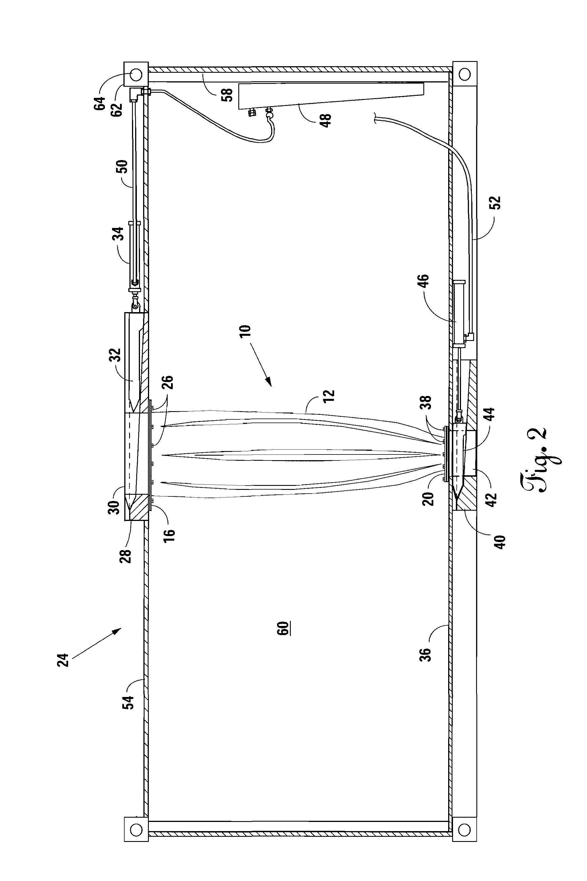
[0024]Referring to the incorporated patent application Ser. No. 13 / 370,401, filed on Feb. 10, 2012, a “Method And Apparatus For Modifying A Cargo Container To Deliver Frac Sand To A Frac Site” is shown and described. The present invention shows another way to modify the cargo container (intermodal container) to deliver a proppant (such as frac sand) to a frac site. Referring to FIG. 1, there is shown a resilient liner represented generally be reference numeral 10 that is long enough to reach from the top to the bottom of an intermodal container. The resilient liner 10 has a bladder 12 that has folds 14 therein for expansion if necessary. At the top of the bladder 12 is a upper mounting bracket 16 with mounting holes 18 there around. The bladder 12 is clamped between an upper portion 16a and a lower portion 16b of upper mounting bracket 16.

[0025]At the bottom of the bladder 12 is a lower mounting bracket 20 with mounting holes 22 therein. The bladder 12 is clamped between an upper po...


PUM

PropertyMeasurementUnit
lengthaaaaaaaaaa
lengthaaaaaaaaaa
lengthaaaaaaaaaa

Abstract

An intermodal container is modified to carry a fracing proppant such as sand from a quarry or source to the frac site. An upper hatch is formed at the top of the intermodal container and a lower hatch is formed in the bottom of the intermodal container. Hydraulically operating sliding gates are placed under the top and bottom hatches. A resilient liner having a bladder extends from the upper hatch to the lower hatch. The bladder expands during loading to receive the proppant therein and contracts when unloading to expel the proppant from the intermodal container.

Description

CROSS-REFERENCE TO RELATED APPLICATIONS[0001]This is an improvement patent application over U.S. patent application Ser. No. 13 / 370,401, filed on Feb. 10, 2012, entitled “Method and Apparatus for Modifying a Cargo Container to Deliver Frac Sand to a Frac Site”, which application has the same inventor and assignee and is incorporated herein by reference.BACKGROUND OF THE INVENTION[0002]1. Field of the Invention[0003]This invention relates to the modification of an intermodal container for the transportation of a granular substance such as sand and, more particularly, the insertion of a resilient liner between a top opening and a bottom opening of a cargo container.[0004]2. Description of the Prior Art[0005]An intermodal container (also called cargo container, freight container, ISO container, shipping container, High-Q container, Sea Cans) is a standardized reusable steel box used for the safe, efficient and secure storage and movement of materials and products within a local contain...

Claims


Application Information

Patent Timeline
Patent Type & Authority Applications(United States)
IPC IPC(8): B65D88/00B23P17/00
CPCB65D88/62B65D90/046B65D90/587Y10T29/49716
Inventor SHEESLEY, JOHN M.
Owner SANDCAN INC
Why Eureka
Try Eureka