
Sliding cover structure

a technology of sliding cover and cover, which is applied in the direction of wing accessories, coupling device connections, wing arrangements, etc., can solve the problems of affecting the operation of these covers is not convenient, and the cover protrudes from the case, so as to facilitate the description of invention, facilitate the operation of the cover, and facilitate the effect of pushing

Inactive Publication Date: 2014-05-01
LITE ON ELECTRONICS (GUANGZHOU) LTD +1
View PDF3 Cites 3 Cited by
  • Summary
  • Abstract
  • Description
  • Claims
  • Application Information

AI Technical Summary

Benefits of technology

The invention allows for easy opening and closing of a container by using two pivots and two uniquely arranged grooves. This is designed to make the use of the container more convenient for the user.

Problems solved by technology

However, after the cover is opened, the cover protrudes from the case and is relatively easily damaged.
However, the accommodating spaces need to accommodate the electrical connector, the covers and the space required for the operation of the covers.
The operation of these covers is not convenient, and sometimes requires fingers to hold, pull and push.
Moreover, the covers protrude from the case when opened, and are susceptible to damage from impact.
These existing designs of electrical appliances are inconvenient, which reduces the overall effect thereof.

Method used


Image

  • Sliding cover structure
  • Sliding cover structure
  • Sliding cover structure

Examples


Embodiment Construction

[0022]The aforementioned illustrations and following detailed descriptions are exemplary for the purpose of further explaining the scope of the present disclosure. Other objectives and advantages related to the present disclosure will be illustrated in the subsequent descriptions and appended drawings.

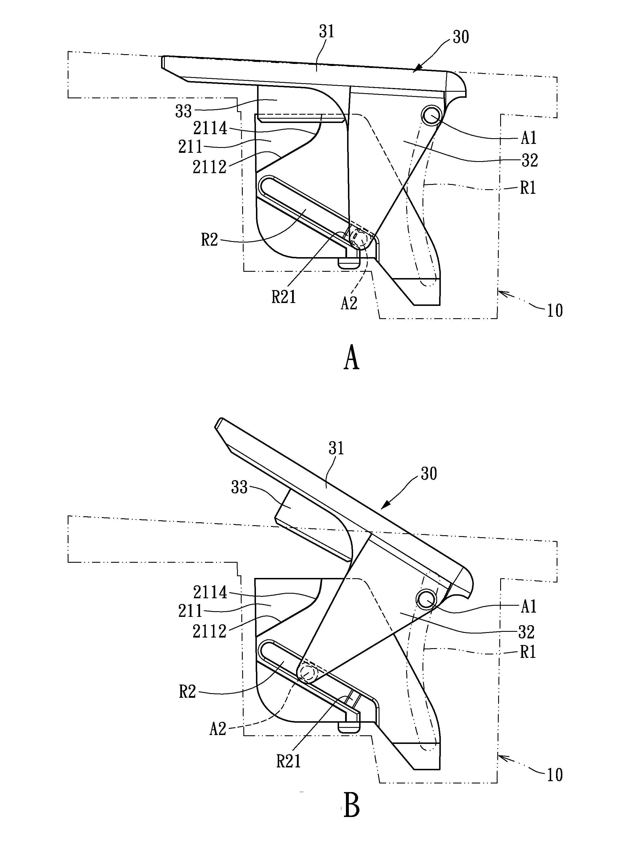
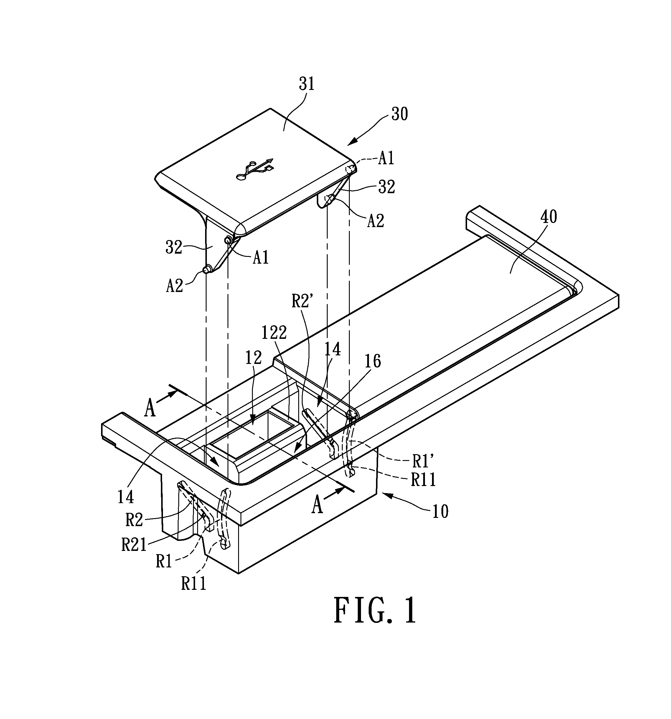
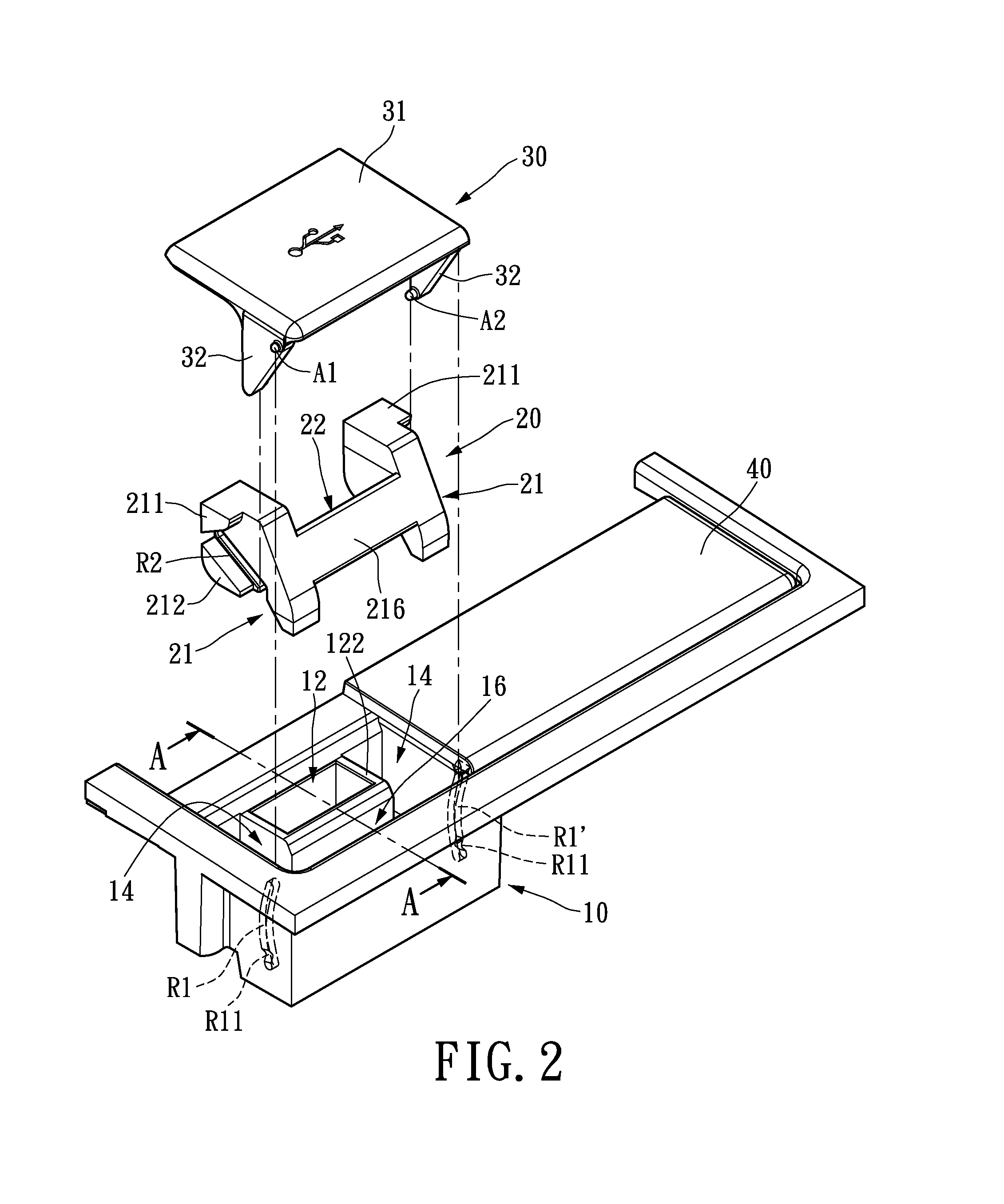
[0023]FIG. 1 is a perspective exploded diagram of the sliding cover structure of the invention. The sliding cover structure of the present embodiment includes an accommodating case 10 and a cover 30. The accommodating case 10 can accommodate objects within, for example an electrical connector (not shown). The cover 30 is movably configured inside the accommodating case 10, such that the cover 30 is movably covering the accommodating case 10 or housed within the accommodating case 10 to expose the contents accommodated therein. The present embodiment uses electrical connectors, such as a USB connector, as an example but the possible contents are not limited thereto.

[0024]The accommodati...


PUM


Abstract

A sliding cover structure having a flappable cover is provided. A first groove and a second groove are disposed on the interior wall of the accommodating case. The cover has a plate portion and a connection wall disposed on the side of the plate portion. The connection wall has a first pivot movably disposed in the first groove, and a second pivot movably disposed in the second groove. The direction of the first groove is overall perpendicular to the plate portion. The second groove is slanted with respect to the first groove. When the first and second pivots slide and rotate respectively within the first and second groove, an effect of moving towards the center is produced to effectively reduce the space required for operation of the structure. Moreover, the cover is housed inside the accommodating case during opening, reducing the risk of impact.

Description

BACKGROUND OF THE INVENTION[0001]1. Field of the Invention[0002]The invention relates to a sliding cover structure, more particularly to a sliding cover structure that is able to quickly open and close a sliding cover therefrom with sliding and rotational function in order to be protected from external impact.[0003]2. Description of Related Art[0004]In order to protect the contents inside the cases, the openings are equipped with covers. A typical cover structure is required to keep the cover securely closed and to allow the cover to be easily opened. Proper use of the cover structure may result in excellent protection effect. However, after the cover is opened, the cover protrudes from the case and is relatively easily damaged.[0005]For example, generally electrical connectors or external sockets are widely applied on electrical devices for connection with other electrical devices. Even electrical appliances such as video players, televisions, refrigerators, and microwave ovens are...

Claims


Application Information

Patent Timeline
IPC IPC(8): E06B3/50
CPCE06B3/5018H01R13/447H01R24/62
Inventor LIN, CHING-CHIH
Owner LITE ON ELECTRONICS (GUANGZHOU) LTD
Learn More