Corner geometry-based wrapping

a geometry and load technology, applied in the field of wrapping loads, can solve the problems of affecting the quality of wrapping materials,

Active Publication Date: 2014-05-01
LANTECH COM
View PDF13 Cites 44 Cited by
  • Summary
  • Abstract
  • Description
  • Claims
  • Application Information

AI Technical Summary

Benefits of technology

[0012]The invention addresses these and other problems associated with the prior art by providing in one aspect a corner geometry-based wrap control that controls the rate at which packaging material is dispensed at least in part based on the geometrical relationship between one or more corners of the load and a packaging material dispenser. In some embodiments of the invention, for example, t

Problems solved by technology

The wrap force, however, is a force that fluctuates as packaging material is dispensed to the load due primarily to the irregular geometry of the load.
In particular, wrappers have historically suffered from packaging material breaks and limitations on the amount of wrap force applied to the load (as determined in part by the amount of pre-stretch used) due to erratic speed changes required to wrap loads.
In other instances, when the demand rate for packaging material by the load is greater than the supply rate of the packaging material by the packaging material dispenser, breakage of the packaging material may occur.
Variations in demand may make it difficult to properly wrap the load, and the problem with variations may be exacerbated when wrapping a load having one or more dimensions that may differ from one or more corresponding dimensions of a preceding load.
The problem may also be exacerbated when wrapping a load having one or more dimensions that vary at one or more locations of the load itself.
With the ever faster wrapping rates demanded by the industry, however, rotation speeds have increased significantly to a point where the concept of sensing changes in force and altering

Method used


Image

  • Corner geometry-based wrapping
  • Corner geometry-based wrapping
  • Corner geometry-based wrapping

Examples


Embodiment Construction

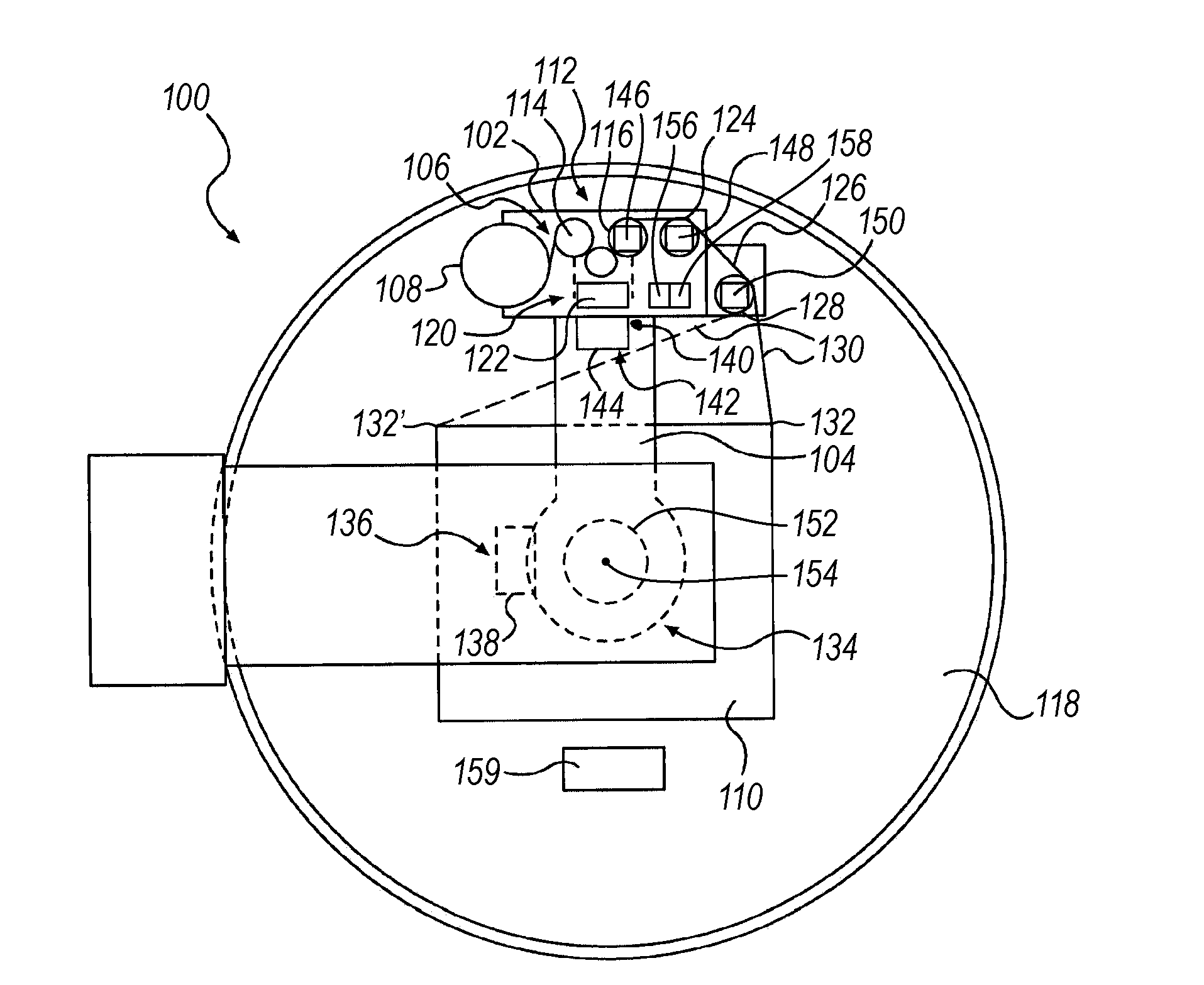
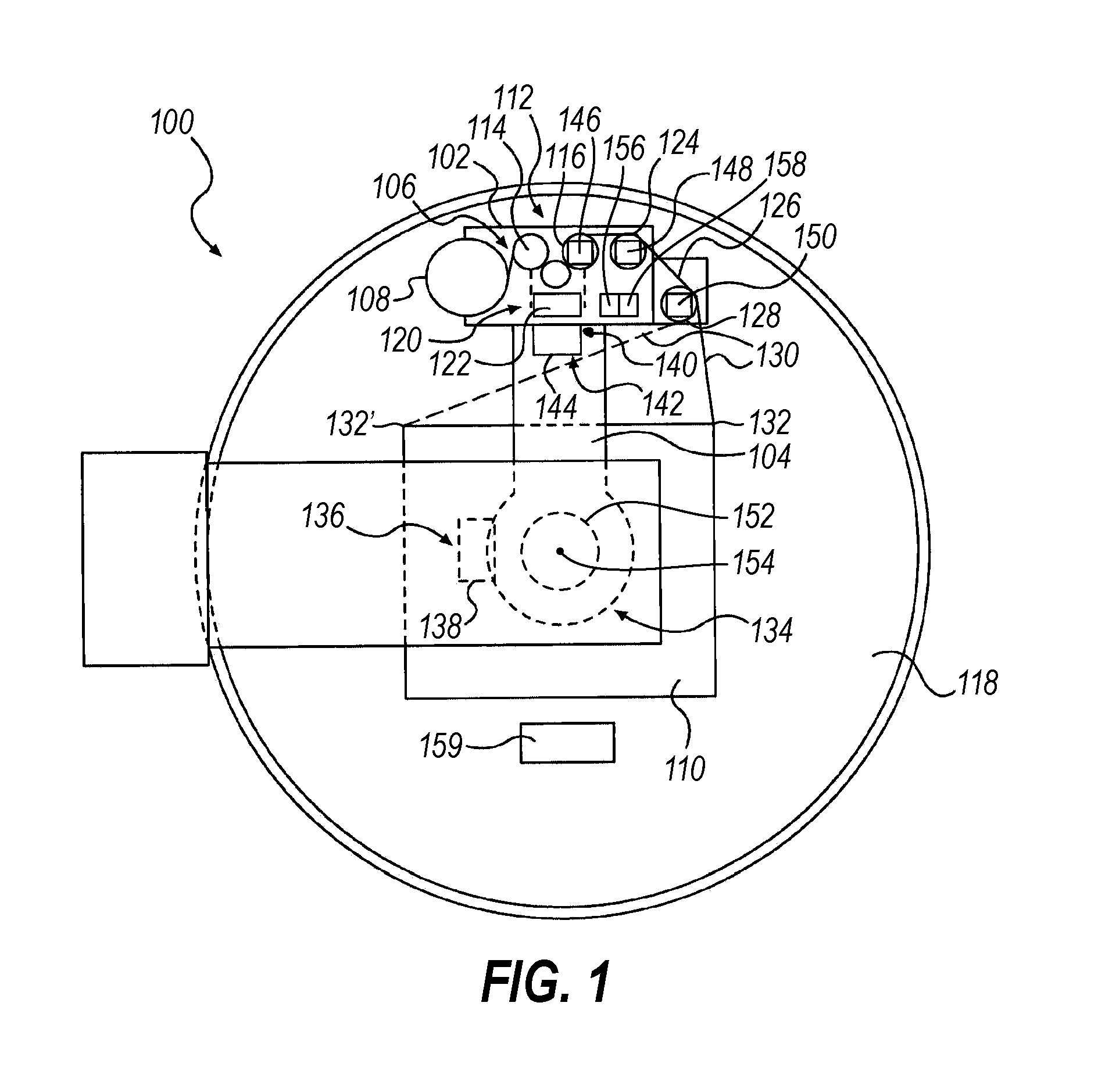
[0040]Embodiments consistent with the invention utilize in one aspect the spatial locations of one or more corners of a load in the control of the rate at which packaging material is dispensed to a load when wrapping the load with packaging material during relative rotation established between the load and a packaging material dispenser. Prior to a discussion of the aforementioned concepts, however, a brief discussion of various types of wrapping apparatus within which the various techniques disclosed herein may be implemented is provided.

[0041]In addition, the disclosures of each of U.S. Pat. No. 4,418,510, entitled “STRETCH WRAPPING APPARATUS AND PROCESS,” and filed Apr. 17, 1981; U.S. Pat. No. 4,953,336, entitled “HIGH TENSILE WRAPPING APPARATUS,” and filed Aug. 17, 1989; U.S. Pat. No. 4,503,658, entitled “FEEDBACK CONTROLLED STRETCH WRAPPING APPARATUS AND PROCESS,” and filed Mar. 28, 1983; U.S. Pat. No. 4,676,048, entitled “SUPPLY CONTROL ROTATING STRETCH WRAPPING APPARATUS AND ...


PUM

PropertyMeasurementUnit
Lengthaaaaaaaaaa
Forceaaaaaaaaaa
Angleaaaaaaaaaa

Abstract

A wrapping apparatus and method utilize a corner geometry-based wrap control that controls the rate at which packaging material is dispensed at least in part based on the geometrical relationship between one or more corners of a load and a packaging material dispenser.

Description

CROSS-REFERENCE TO RELATED APPLICATIONS[0001]This application claims the benefit of and priority to U.S. Provisional Application Ser. No. 61 / 718,429 filed on Oct. 25, 2012 by Patrick R. Lancaster III et al., and entitled “ROTATION ANGLE-BASED WRAPPING,” and U.S. Provisional Application Ser. No. 61 / 718,433 filed on Oct. 25, 2012 by Patrick R. Lancaster III et al., and entitled “EFFECTIVE CIRCUMFERENCE-BASED WRAPPING,” which applications are incorporated by reference in their entirety.FIELD OF THE INVENTION[0002]The invention generally relates to wrapping loads with packaging material through relative rotation of loads and a packaging material dispenser, and in particular, to the control of the rate in which packaging material is dispensed during wrapping.BACKGROUND OF THE INVENTION[0003]Various packaging techniques have been used to build a load of unit products and subsequently wrap them for transportation, storage, containment and stabilization, protection and waterproofing. One sy...

Claims


Application Information

Patent Timeline
IPC IPC(8): B65B57/04B65B11/04
CPCB65B57/04B65B11/045B65B11/025
Inventor LANCASTER, III, PATRICK R.MITCHELL, MICHAEL P.MCCRAY, JEREMY D.JOHNSON, RICHARD L.
Owner LANTECH COM
Why Eureka
Try Eureka