
Expandable Fusion Device and Method of Installation Thereof

a fusion device and expandable technology, applied in the field of expandable fusion devices, can solve the problems of difficult installation of the fusion device in the distracted intervertebral space by the surgeon, drawbacks of the known conventional fusion device and methodology, etc., and achieve the effect of restoring spinal stability

Active Publication Date: 2014-05-01
GLOBUS MEDICAL INC
View PDF2 Cites 130 Cited by
  • Summary
  • Abstract
  • Description
  • Claims
  • Application Information

AI Technical Summary

Benefits of technology

The present invention provides an expandable fusion device that can be installed inside an intervertebral disc space to maintain normal disc spacing and restore spinal stability. This device consists of a body portion, first and second endplates that can be moved in a direction away or towards the body portion, and can be expanded or unexpanded. The device can be deployed in the unexpanded or expanded configuration. The technical effect of this invention is that it provides a reliable and effective tool for spinal fusion procedures.

Problems solved by technology

However, there are drawbacks associated with the known conventional fusion devices and methodologies.
For example, present methods for installing a conventional fusion device often require that the adjacent vertebral bodies be distracted to restore a diseased disc space to its normal or healthy height prior to implantation of the fusion device.
This difference in height can make it difficult for a surgeon to install the fusion device in the distracted intervertebral space.

Method used


Image

  • Expandable Fusion Device and Method of Installation Thereof
  • Expandable Fusion Device and Method of Installation Thereof
  • Expandable Fusion Device and Method of Installation Thereof

Examples


Embodiment Construction

[0085]The following description of the preferred embodiment(s) is merely exemplary in nature and is in no way intended to limit the invention, its application, or uses.

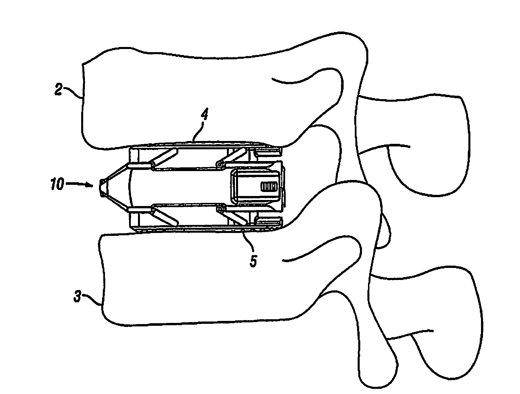
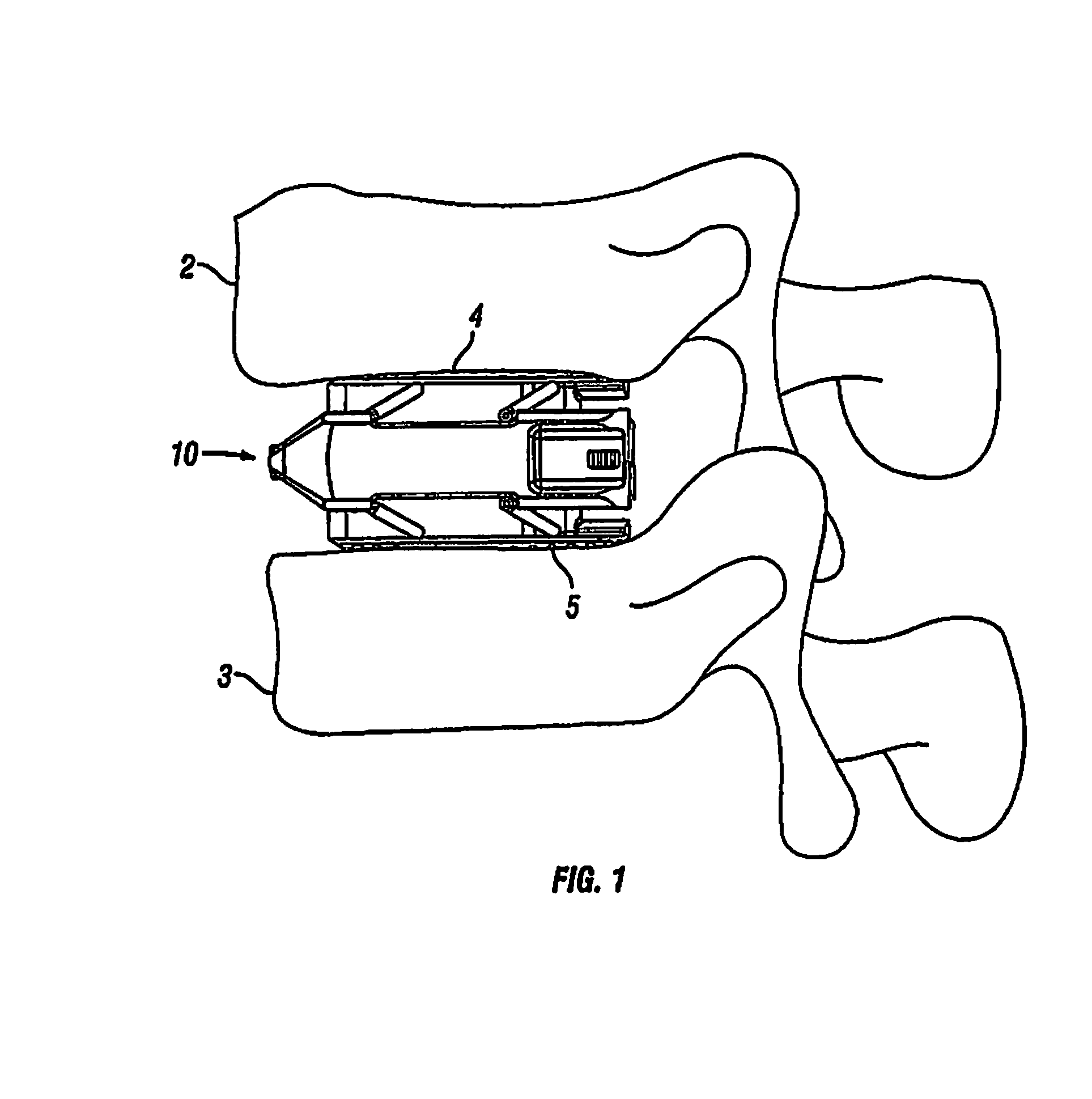
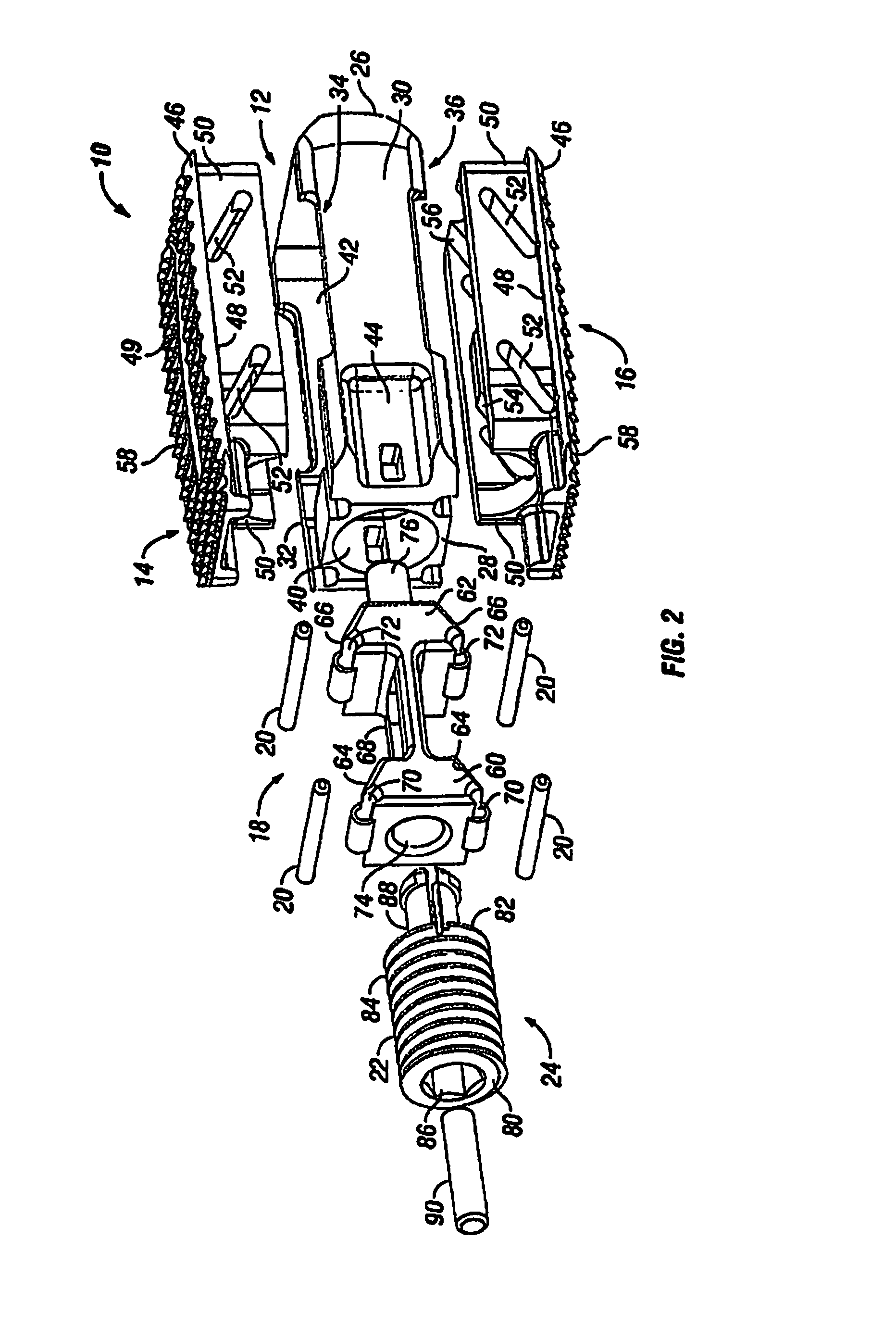
[0086]A spinal fusion is typically employed to eliminate pain caused by the motion of degenerated disk material. Upon successful fusion, a fusion device becomes permanently fixed within the intervertebral disc space. Looking at FIG. 1, an exemplary embodiment of an expandable fusion device 10 is shown between adjacent vertebral bodies 2 and 3. The fusion device 10 engages the endplates 4 and 5 of the adjacent vertebral bodies 2 and 3 and, in the installed position, maintains normal intervertebral disc spacing and restores spinal stability, thereby facilitating an intervertebral fusion. The expandable fusion device 10 can be manufactured from a number of materials including titanium, stainless steel, titanium alloys, non-titanium metallic alloys, polymeric materials, plastics, plastic composites, PEEK, ceramic, and ela...


PUM


Abstract

The present invention provides an expandable fusion device capable of being installed inside an intervertebral disc space to maintain normal disc spacing and restore spinal stability, thereby facilitating an intervertebral fusion. In one embodiment, the fusion device includes a body portion, a first endplate, and a second endplate, the first and second endplates capable of being moved in a direction away from the body portion into an expanded configuration or capable of being moved towards the body portion into an unexpanded configuration. The fusion device is capable of being deployed and installed in both configurations.

Description

CROSS-REFERENCE TO RELATED APPLICATIONS[0001]This patent application is a continuation-in-part application claiming priority to U.S. patent application Ser. No. 13 / 451,230, filed Apr. 19, 2012, which is a continuation of U.S. patent application Ser. No. 13 / 440,158, filed Apr. 5, 2012, which is a continuation-in-part application of U.S. patent application Ser. No. 12 / 823,736, filed Jun. 25, 2010, and a continuation-in-part application claiming priority to U.S. patent application Ser. No. 13 / 273,994, filed Oct. 14, 2011, which is a continuation of U.S. patent application Ser. No. 12 / 579,833, filed Oct. 15, 2009, now issued as U.S. Pat. No. 8,062,375, the entire contents of which are incorporated by reference.FIELD OF THE INVENTION[0002]The present invention relates to the apparatus and method for promoting an intervertebral fusion, and more particularly relates to an expandable fusion device capable of being inserted between adjacent vertebrae to facilitate the fusion process.BACKGROU...

Claims


Application Information

Patent Timeline
Patent Type & Authority Applications(United States)
IPC IPC(8): A61F2/44
CPCA61F2/4611A61F2002/30482A61F2002/30405A61F2002/30538A61F2002/4624A61F2002/4627A61F2/4455A61F2/447A61F2/4684A61F2002/30207A61F2002/3021A61F2002/30265A61F2002/30365A61F2002/30367A61F2002/30372A61F2002/30373A61F2002/30387A61F2002/30484A61F2002/30492A61F2002/30495A61F2002/30507A61F2002/30517A61F2002/3052A61F2002/30523A61F2002/3055A61F2002/30551A61F2002/30556A61F2002/30578A61F2002/30579A61F2002/30596A61F2002/30598A61F2002/30601A61F2002/30841A61F2002/30904A61F2002/4475A61F2310/00017A61F2310/00023A61F2310/00179A61F2002/30169A61F2/4603A61F2002/30593A61F2002/30594A61F2002/30525A61F2002/30843
Inventor GLERUM, CHADMATTHEWS, JOHNDAVENPORT, DAN
Owner GLOBUS MEDICAL INC
Learn More