Print head and inkjet printing apparatus

a printing head and inkjet technology, applied in printing and other directions, can solve problems such as contamination of print media, and achieve the effect of suppressing image degradation and reducing satellites

Active Publication Date: 2014-05-08
CANON KK
View PDF3 Cites 3 Cited by
  • Summary
  • Abstract
  • Description
  • Claims
  • Application Information

AI Technical Summary

Benefits of technology

[0013]According to the present invention, the ink tail can be shortened to reduce the satellite, and the deviation in a landing-on position of the ejected liquid on the print medium can be prevented to suppress image degradation due to the deviation.

Problems solved by technology

There are some cases where degradation of image quality is caused by the event that the satellite lands on a print medium at a large distance from the main drop or the satellite loses its speed before reaching the print medium to be formed as a floating liquid drop (hereinafter, called a mist), possibly causing contamination of the print medium.

Method used


Image

  • Print head and inkjet printing apparatus
  • Print head and inkjet printing apparatus
  • Print head and inkjet printing apparatus

Examples


first embodiment

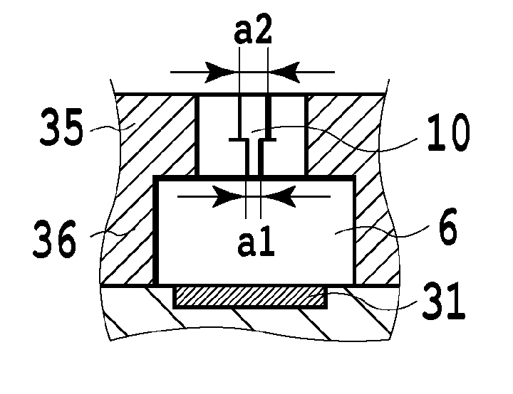
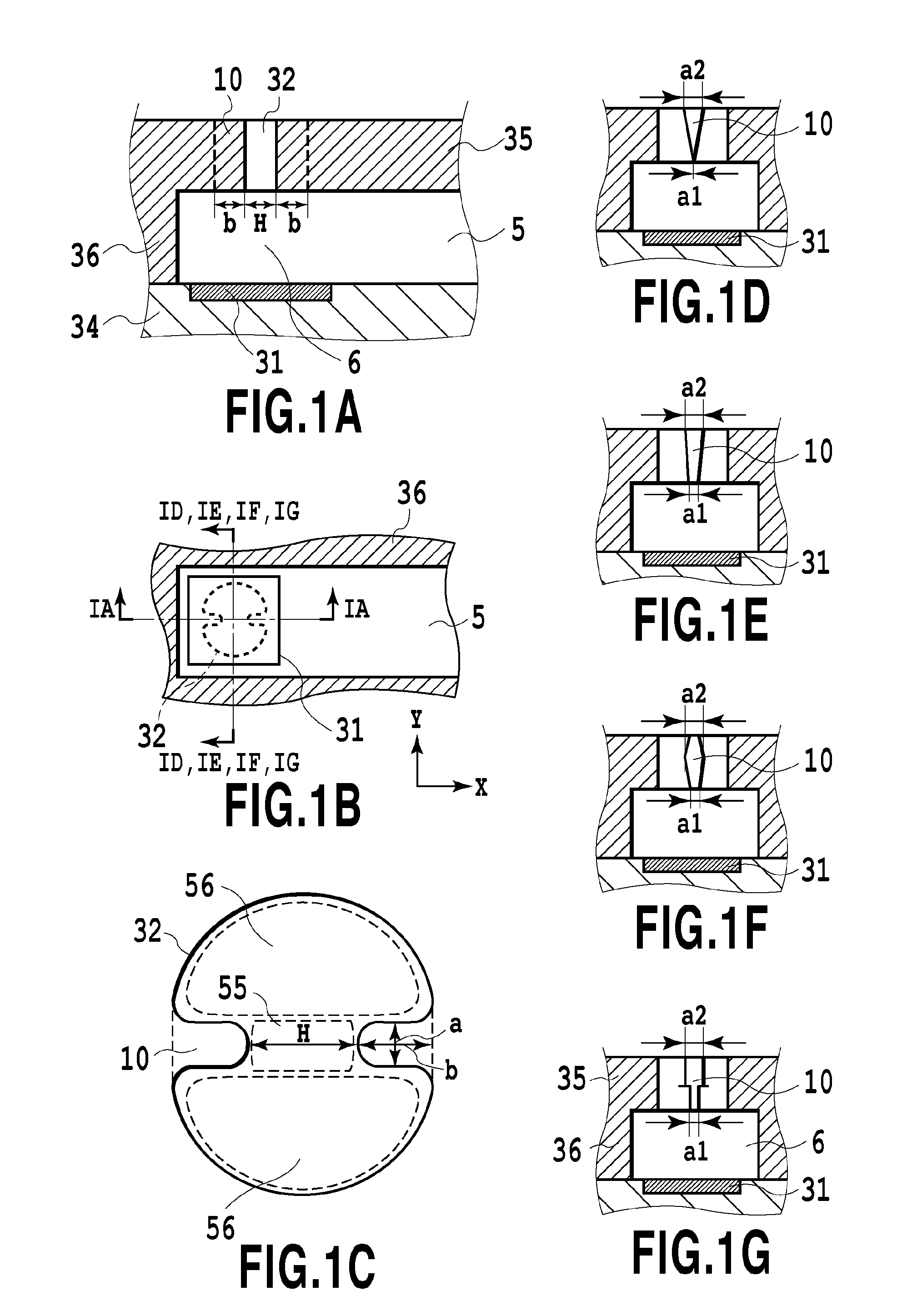
[0067]FIG. 1A to FIG. 1D show a major part of the print head according to the first embodiment in the present invention. FIG. 1A is a cross section taken along an ejection direction of the liquid in the vicinity of the ejection opening 32 in the print head and is a diagram taken along a longitudinal direction (hereinafter, called also an X direction) of a flow passage 5 communicating the supply port 33 of the liquid and the ejection opening 32. FIG. 1B is a schematic diagram of each configuration of the heater 31 and the flow passage 5 as viewed from a side of the ejection opening 32. FIG. 1C shows a configuration of the ejection opening 32 at an ejection opening plate surface 35a (hereinafter, called also an atmosphere-side opening face). FIG. 1D is a cross section taken along an ejection direction of the liquid in the vicinity of the ejection opening 32 in the print head and is a diagram taken in a direction perpendicular to the longitudinal direction of the flow passage 5, that i...

second embodiment

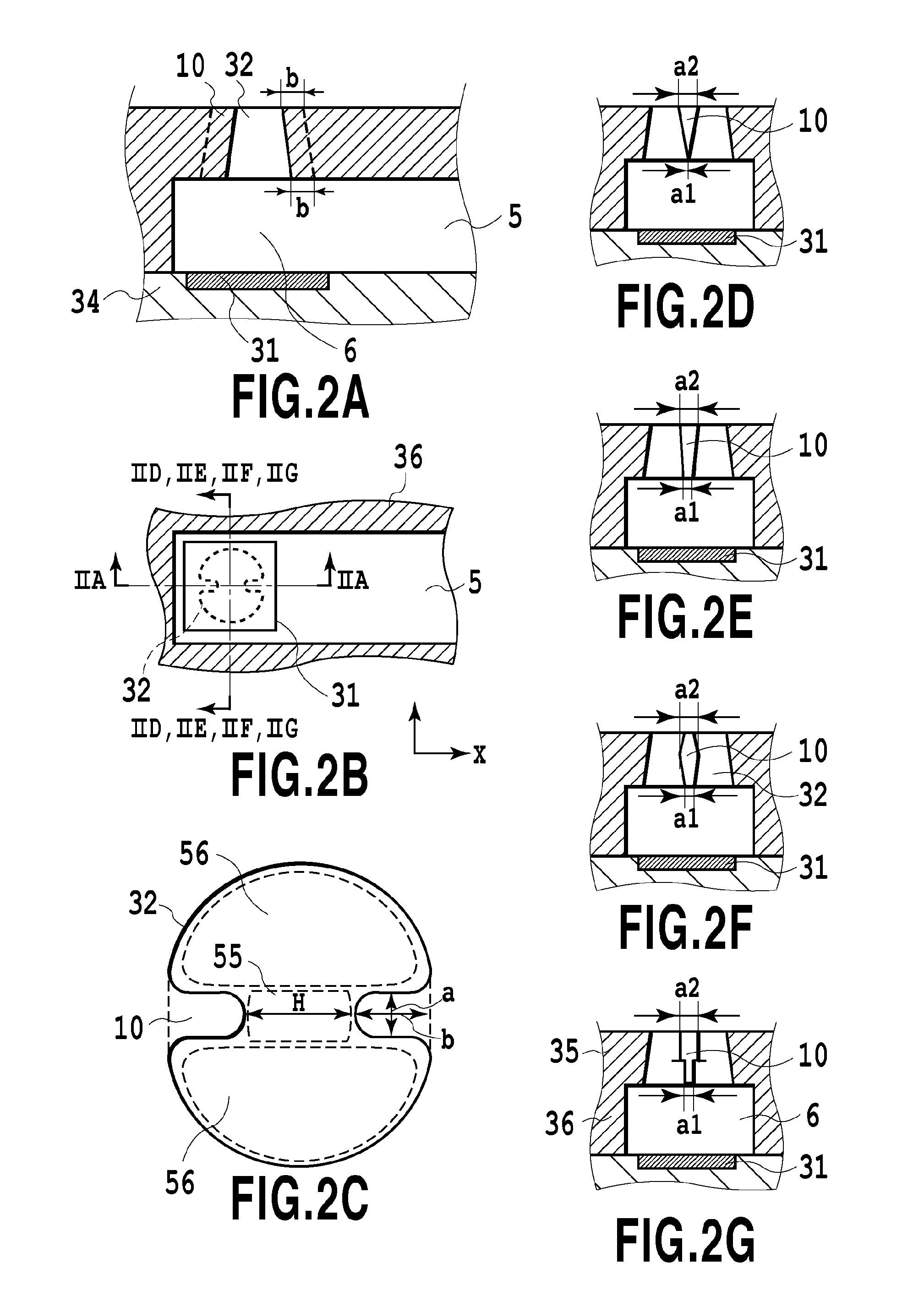
[0085]FIG. 2A to FIG. 2G show a second embodiment in the present invention, and correspond to FIG. 1A to FIG. 1G in the first embodiment. In regard to components identical to those in the first embodiment, the explanation of the first embodiment thereof can be applied.

[0086]By referring to FIG. 2C, a print head in the second embodiment is provided with a substantially circular ejection opening having two opposing projections front ends of which are spaced by a distance H and each of which has a width a and a length (projection distance from a virtual circumference of a circle) b, which is similar to the first embodiment as viewed from an outside. By referring to FIG. 2A, the projection 10 extends from the atmosphere-side opening face to the bubble generating chamber 6-side opening face of the ejection opening 32. With this configuration, the projection 10 in the second embodiment can locally leave the liquid in the ejection opening 32 between the front ends of the projections 10 in ...

third embodiment

[0089]FIG. 3A to FIG. 3G show a third embodiment in the present invention. In regard to components identical to those in the first or second embodiment, the explanation in the first or second embodiment thereof can be applied.

[0090]The third embodiment will be explained by comparison with the second embodiment. In the second embodiment, by referring to FIG. 2A and FIG. 2C, the length b of the projection 10 (projection distance from a virtual circumference of a circle) is constant from the atmosphere-side opening face to the bubble generating chamber-side opening face of the ejection opening. Therefore the distance H between the front ends of the projections 10 becomes larger from the atmosphere-side opening face toward the bubble generating chamber 6-side opening face. On the other hand, in the third embodiment, a length b of the projection 10 (projection distance from a virtual circumference of a circle) changes such that a distance H between the front ends of the projections 10 be...


PUM


Abstract

The print head includes an energy generating element, a chamber for accommodating liquid, and an ejection opening arranged in a position corresponding to the energy generating element. The ejection opening includes at least one projection projecting inside of the ejection opening, the ejection opening having a first region between a front end of the projection and an inner wall of the ejection opening positioned at the shortest distance from the front end, and second regions positioned in both sides of the projection and different from the first region, and when a width of the projection at a chamber-side opening face is represented as a1 and the maximum width of the projection is represented as a2, a relation a1<a2 is established and the width of the projection decreases gradually or step by step from a position having the width of a2 to the chamber-side opening face.

Description

TECHNICAL FIELD[0001]The present invention relates to a print head which ejects liquid drops on a medium for printing, and an inkjet printing apparatus using the print head.BACKGROUND ART[0002]As to a method of ejecting a liquid of ink or the like, there is known a method of using an ejection energy-generating element such as a heat generating element (heater) or the like to bring a liquid to a boil to generate an air bubble a pressure of which causes a liquid drop to be ejected from an ejection opening in the print head. In regard to such a liquid drop ejecting method, there are provided a bubble through jet (hereinafter, called also BTJ) ejection method in which an air bubble in the print head is communicated with the atmosphere in the liquid drop ejection process and a bubble jet ejection method in which the air bubble in the print head is not communicated with the atmosphere in the liquid drop ejection process. FIG. 8A to FIG. 8H are pattern diagrams showing a general ejection p...

Claims


Application Information

Patent Timeline
Patent Type & Authority Applications(United States)
IPC IPC(8): B41J2/14
CPCB41J2/14B41J2/1404B41J2002/14169B41J2002/14475
Inventor TOMIZAWA, KEIJIOIKAWA, MASAKI
Owner CANON KK
Why Eureka
Try Eureka