Attachment arrangement for composite wheels

a technology for attaching arrangements and wheels, applied in the direction of bolts, washers, fastening means, etc., can solve the problems of reducing the clamping load of joints and further torque loss, and achieve the effect of increasing the clamping contact area and increasing the area

Active Publication Date: 2014-06-26
CARBON REVOLUTION
View PDF4 Cites 9 Cited by
  • Summary
  • Abstract
  • Description
  • Claims
  • Application Information

AI Technical Summary

Benefits of technology

[0008]The attachment arrangement of the present invention enables the composite wheel to have an extremely stiff fastening to the mount relative to the fastening nut without damaging the composite wheel. This can reduce or substantially eliminate loss of fastening torque associated with any external loading conditions in the attachment arrangement. Progressive loss of fastening torque can result in the bolted joint to loosen and the fastener to rotate resulting in further torque loss and reduction of the joint clamping load.
[0013]The sleeve aperture is preferably sized to allow at least a portion of the sleeve to move through the sleeve aperture. The sleeve can therefore be designed to provide a clearance between the bottom of the sleeve and the surface surrounding the sleeve aperture. There is preferably a light press fit between the sleeve and the element which includes the sleeve aperture so that the sleeve can slide through the sleeve aperture when the attachment arrangement is compressed. This reduces the possibility of the sleeve making contact with the mount and transferring some of the clamping load to the mount or radially within the attachment aperture and / or sleeve aperture. It is preferable for all the compression loading from the fastener to go through the composite structure.
[0017]The distal end of the sleeve can have a fixing feature which prevents withdrawal of the sleeve through the sleeve aperture of the backing plate. This fixing feature can be any element or formation. In one embodiment, the distal end of the sleeve is inserted through the sleeve aperture and then the end is deformed to a greater size than the sleeve aperture. This deformation can have any shape or configuration. In one embodiment, the distal edge is deformed to form a rolled edge. This deformation provides the added advantage of adding an amount of compressive pre-load to the joint during assembly. This arrangement still allows the sleeve to slide relative to the backing plate in one direction but prevents the whole assembly from falling apart when the fastener element is removed.
[0018]The fastening washer section of the attachment arrangement of the present invention is configured to provide an increased clamping contact area with the surface of the composite wheel surrounding the attachment aperture and thereby increase the area through which the clamping force is applied to that area.
[0020]In some embodiments, the engagement surface is angled or curved relative to the fastening axis. The angle or curved shape of the engagement surface of the fastening washer can provide an additional feature that enables the force to be distributed away from the edge of a surface located about the attachment aperture and is more evenly distributed on the composite structure.

Problems solved by technology

Progressive loss of fastening torque can result in the bolted joint to loosen and the fastener to rotate resulting in further torque loss and reduction of the joint clamping load.

Method used


Image

  • Attachment arrangement for composite wheels
  • Attachment arrangement for composite wheels
  • Attachment arrangement for composite wheels

Examples


Embodiment Construction

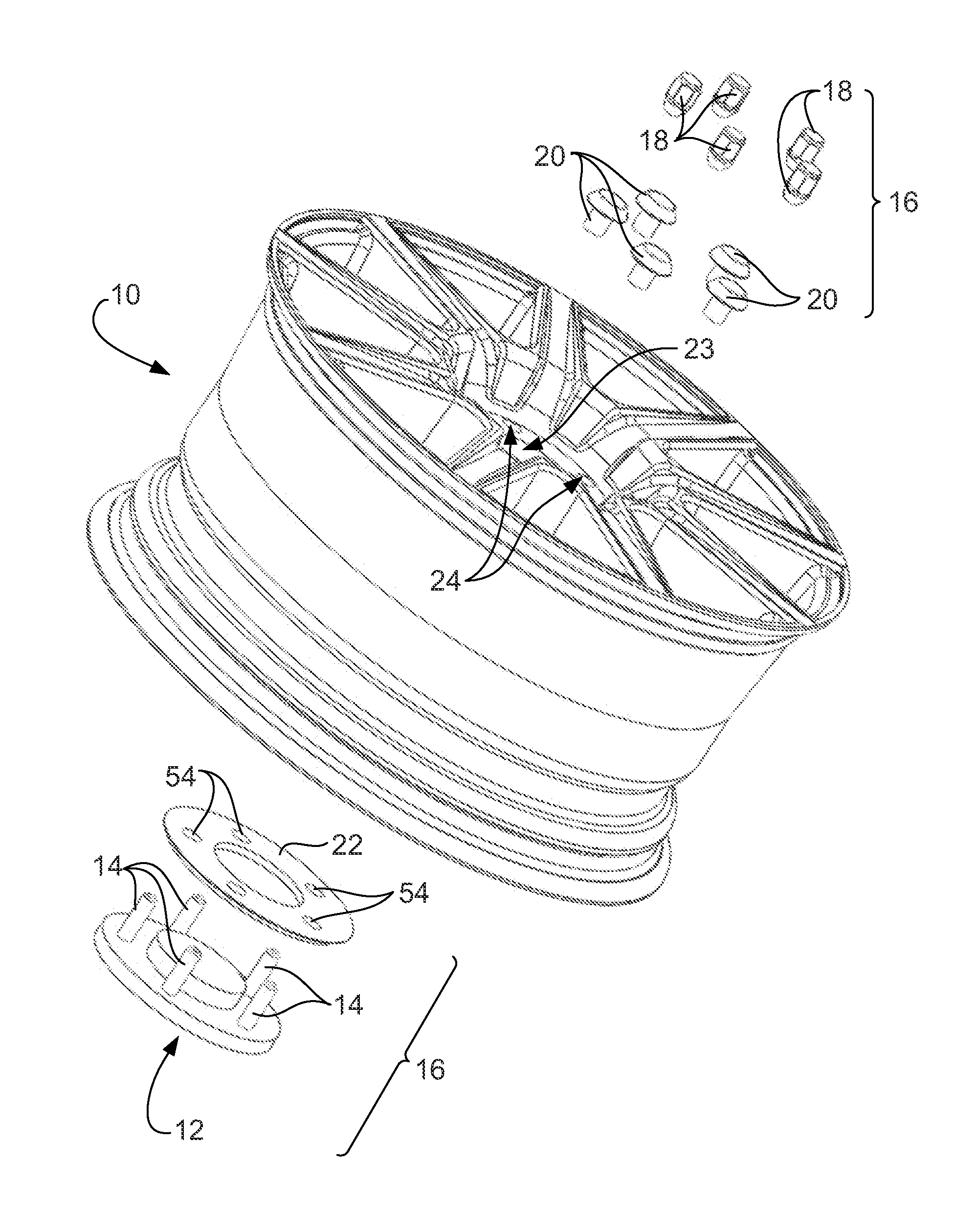
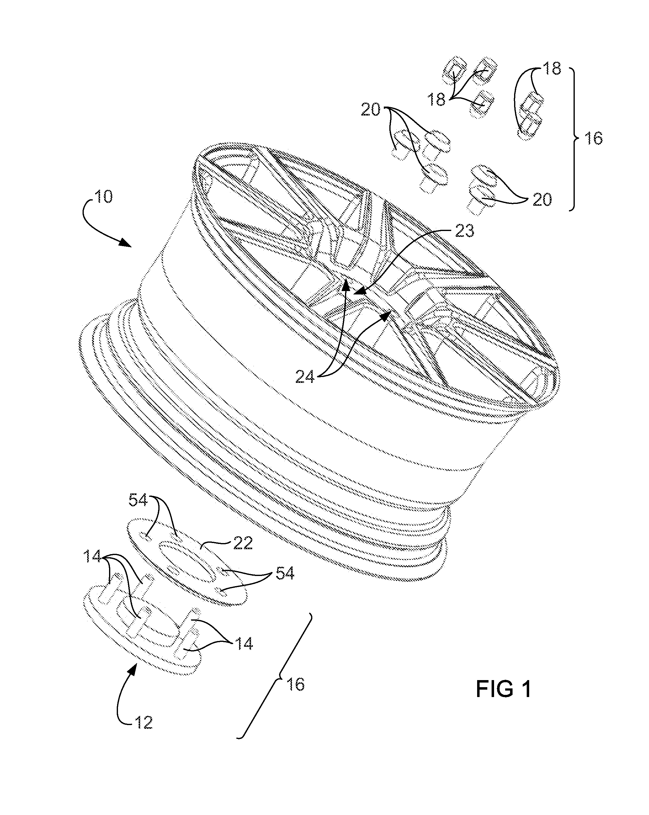
[0035]FIG. 1 illustrates a carbon fibre composite wheel 10 which is attached to a wheel mount (or wheel hub) 12 through wheel studs 14 using an attachment arrangement 16 according to a first preferred embodiment of the present invention.

[0036]The illustrated attachment arrangement 16 comprises fastening nuts 18 which can be fastened onto the wheel studs 14, fastening washers 20 and a backing plate 22.

[0037]The composite wheel 10 is a one piece carbon fibre wheel. The hub portion 23 of the wheel 10 includes five attachment apertures 24 through which the wheels studs 14 of the wheel mount 12 are inserted when the wheel 10 is mounted on the wheel mount 12. Each of the wheel studs 14 are an elongate externally threaded pin having a complementary thread to a threaded internal bore 24 (FIG. 3) of each of the fastening nuts 18.

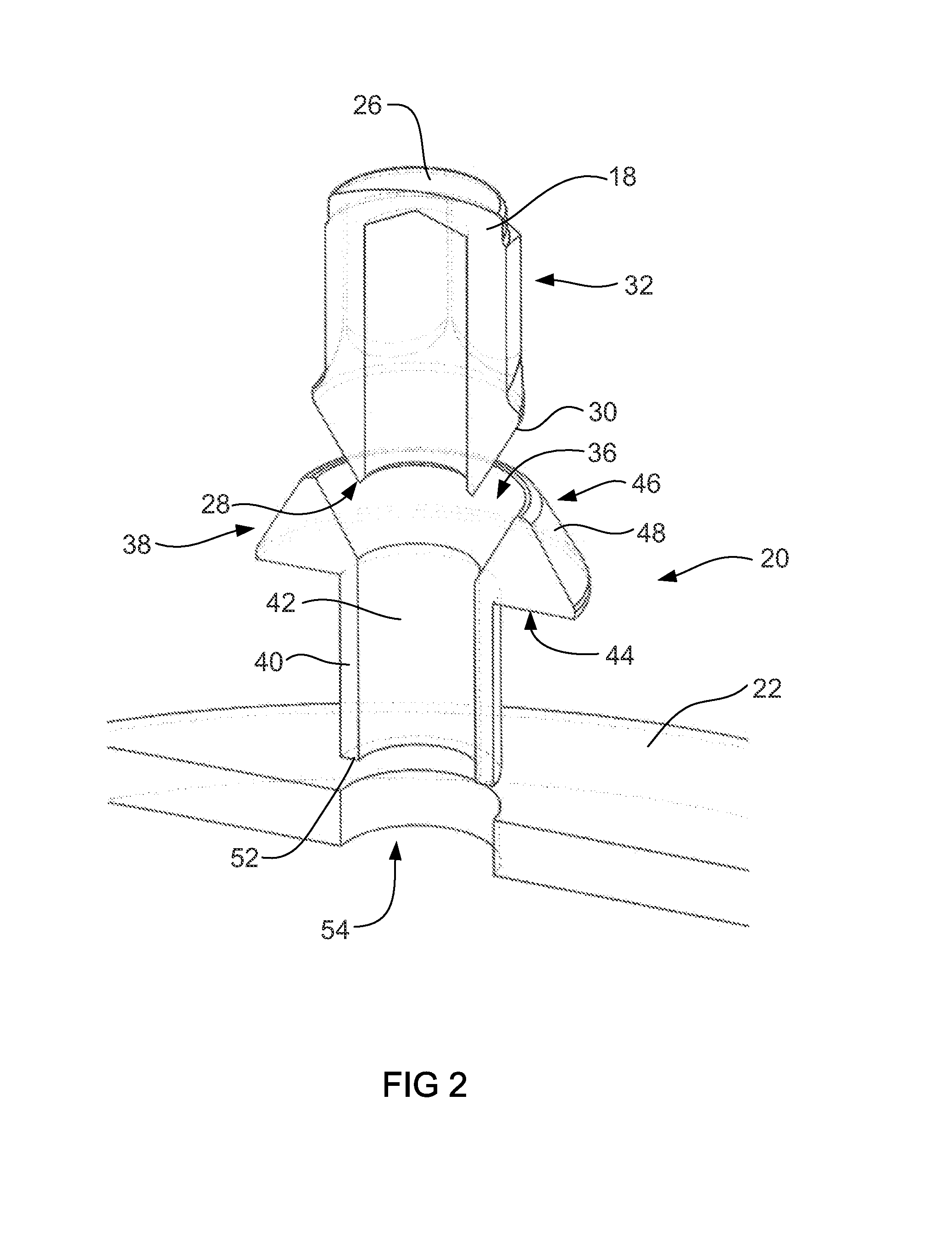
[0038]As best shown in FIGS. 2 and 3, each fastening nut 18 is a cylindrical cap including a top 26 and a base 28 which annularly extends around the internal bore 24...


PUM


Abstract

The present invention provides an attachment arrangement for use in attaching at least one composite wheel to a mount using an elongate fastener element and a fastening nut which can be fastened on the elongate fastener element. The attachment arrangement is used with a composite wheel that includes at least one attachment aperture through which the elongate fastener element is inserted. The attachment arrangement includes a fastening washer having a fastening aperture through which the elongate fastener element can be inserted when in use. The fastening aperture includes a radially central fastening axis. The fastening washer also has a base configured to face a surface of the composite wheel about the attachment aperture. In addition, the fastening washer has a fastening side facing substantially axially outwardly from the attachment aperture. The fastening side includes at least one engagement surface configured to operatively engage a complementary portion of the fastening nut when the fastening nut is assembled on the elongate fastener element. The fastening arrangement also includes a sleeve which extends axially relative to the fastening axis outwardly from the base about the fastening aperture. The sleeve is configured to extend into the attachment aperture of the composite wheel. The sleeve also includes a distal end configured to be received in a complementary shaped sleeve aperture located in the mount or in an element located adjacent the mount.

Description

FIELD OF THE INVENTION[0001]The present invention generally relates to an arrangement for attaching one or more composite wheels to a mount. The invention is particularly applicable to attachment arrangements for carbon fibre wheels and it will be convenient to hereinafter disclose the invention in relation to that exemplary application.BACKGROUND TO THE INVENTION[0002]The following discussion of the background to the invention is intended to facilitate an understanding of the invention. However, it should be appreciated that the discussion is not an acknowledgement or admission that any of the material referred to was published, known or part of the common general knowledge as at the priority date of the application.[0003]Attaching composite structures to other components or structures can be challenging. Composite structures, such as carbon fibre components, are generally extremely stiff in the fibre direction, but can have less strength perpendicular to the fibre direction. Attac...

Claims


Application Information

Patent Timeline
Patent Type & Authority Applications(United States)
IPC IPC(8): B60B3/14B60B3/16
CPCB60B3/16B60B3/145B60B3/147B60B5/02B60B27/0052B60B2360/36B60B2900/212B60B2900/325F16B19/02F16B43/00
Inventor DINGLE, MATTHEW EDWARDGASS, DONALD BRETTDENMEAD, ASHLEY JAMES
Owner CARBON REVOLUTION
Why Eureka
Try Eureka