Seat Base For Aircraft

a seat base and aircraft technology, applied in the direction of seat arrangements, machine supports, emergency equipment, etc., can solve problems such as injuries to the occupants

Active Publication Date: 2014-07-10
TEXTRON INNOVATIONS
View PDF11 Cites 33 Cited by
  • Summary
  • Abstract
  • Description
  • Claims
  • Application Information

AI Technical Summary

Benefits of technology

[0006]A seat base for use in aircraft according to one embodiment of the current invention comprises a first cross member, a second cross member, a first leg, a second leg, and a base plate having a first bendable tab and a second bendable tab facing away from the first tab. The first cross member, the second cross member, and the base plate are each configured to be secured to the first and second legs in an extended position and a retracted position. The first and second legs are configured to be secured to seat feet and floor tracking rails. The first and second cross members are secured to the base plate so as to allow for selective rotation of the first and second cross members in response to relative vertical movement of the first leg with respect to the second leg.
[0007]According to another embodiment, a seat base comprises a first leg, a second leg, a first cross member, a second cross member, and a base plate. The first leg has a side surface and a top surface. A first proximal slot, a first central slot and a first distal slot extends through the first leg side surface. A first proximal opening upwardly adjacent the first proximal slot, a first central opening upwardly adjacent the first central slot, and a first distal opening upwardly adjacent the first distal slot extends through the first leg top surface. The second leg similarly has a side surface and a top surface. A second proximal slot, a second central slot, and a second distal slot extends through the second leg side surface. A second proximal opening upwardly adjacent the second proximal slot, a second central o

Problems solved by technology

Aircraft seats are generally configured to absorb dynamic loads (e.g., during an emergency landing or a c

Method used


Image

  • Seat Base For Aircraft
  • Seat Base For Aircraft
  • Seat Base For Aircraft

Examples


Embodiment Construction

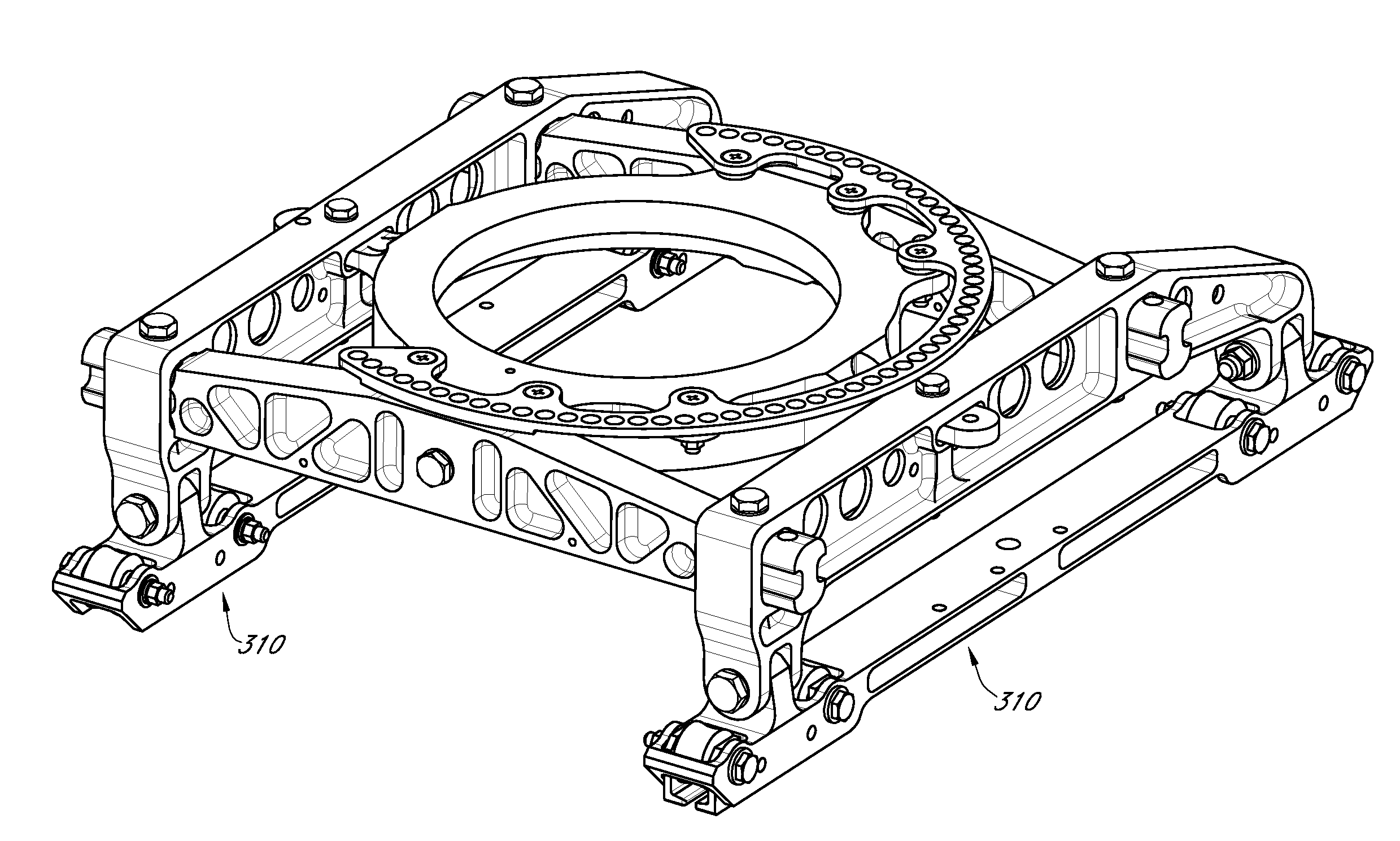
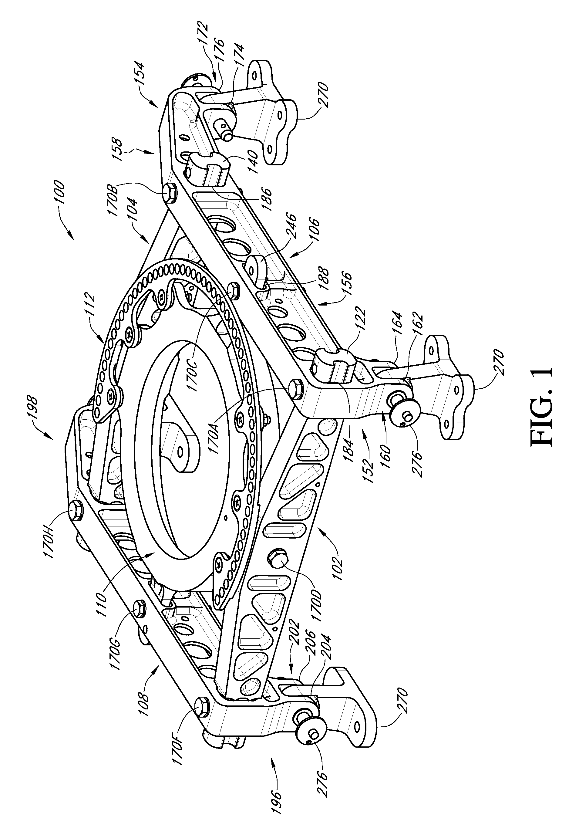
[0017]Embodiments of the present invention provide systems and methods for the construction and assembly of a multi-configurable seat base primarily for use in aircraft. FIG. 1 shows an embodiment 100 of a seat base in accordance with the teachings of the current invention. As can be seen, the seat base 100 includes a first cross member 102, a second cross member 104, a first leg 106, a second leg 108, a base plate 110, and a swivel ring 112.

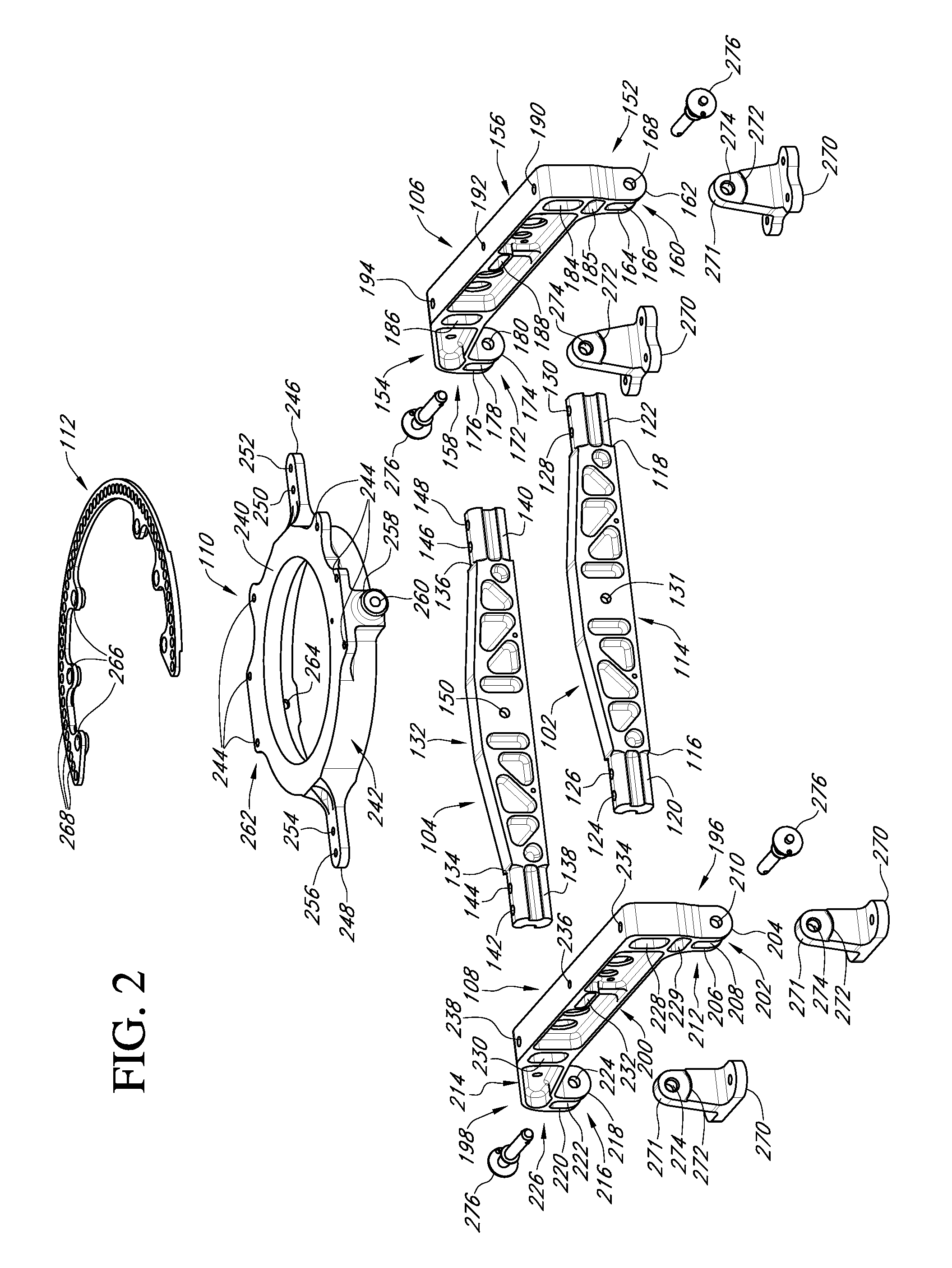
[0018]FIG. 2 shows these components disassembled. The first cross member 102 may have a central portion 114 having edges 116 and 118. A side member 120 may extend from the edge 116, and a side member 122 may extend from the edge 118. The side member 120, towards its upper face, may have a first opening 124 and a second opening 126. These openings 124, 126 may extend through the lower face of side member 120. The spacing between the first and second openings 124, 126 may be between 0.5 and three inches, and preferably is approximately 1.5 inches....


PUM


Abstract

A seat base for use in aircraft has a first cross member, a second cross member, a first leg, a second leg, and a base plate having a first bendable tab and a second bendable tab facing away from the first tab. The first cross member, the second cross member, and the base plate are each configured to be secured to the first and second legs in an extended position and a retracted position. The first and second legs are configured to be secured to seat feet and floor tracking rails. The first and second cross members are secured to the base plate so as to allow for selective rotation of the first and second cross members in response to relative vertical movement of the first leg with respect to the second leg.

Description

BACKGROUND OF THE INVENTION[0001]1. Field of the Invention[0002]The invention relates generally to the field of aircraft interior equipment. More specifically, the invention relates to a multi-configurable base for securement of seats, tables and other aircraft interior equipment.[0003]2. Description of the Related Art[0004]Aircraft seats are generally configured to absorb dynamic loads (e.g., during an emergency landing or a crash), as collapsing of the seats in response to dynamic loads may cause serious injury to the occupants. Several designs for seat bases have heretofore been disclosed to enable the seats to better absorb such loads. For example, U.S. Pat. No. 7,182,403 to Williamson et al. discloses a seat base having angled leg members which aid the base rails of the seat absorb energy during a dynamic event.[0005]Some aircraft seats may be arranged in multiple configurations. For example, U.S. patent application Ser. No. 12 / 048,646 by Kennedy et al. discloses a base for air...

Claims


Application Information

Patent Timeline
IPC IPC(8): B64D11/06B60N2/90
CPCB64D11/0696B64D11/06B64D11/0619B64D11/0689B64D25/04
Inventor WARD, BARRYHOVERSON, DANIEL JAMESBHONGE, PRASANNAKUMARPHI, THANG CHIEN
Owner TEXTRON INNOVATIONS
Why Eureka
Try Eureka