Supercharge Your Innovation With Domain-Expert AI Agents!

Display device

a display device and display technology, applied in the field of display devices, can solve the problems of increasing production costs, signal delay, and complicating the manufacturing process

Active Publication Date: 2014-07-24
SAMSUNG DISPLAY CO LTD
View PDF4 Cites 1 Cited by
  • Summary
  • Abstract
  • Description
  • Claims
  • Application Information

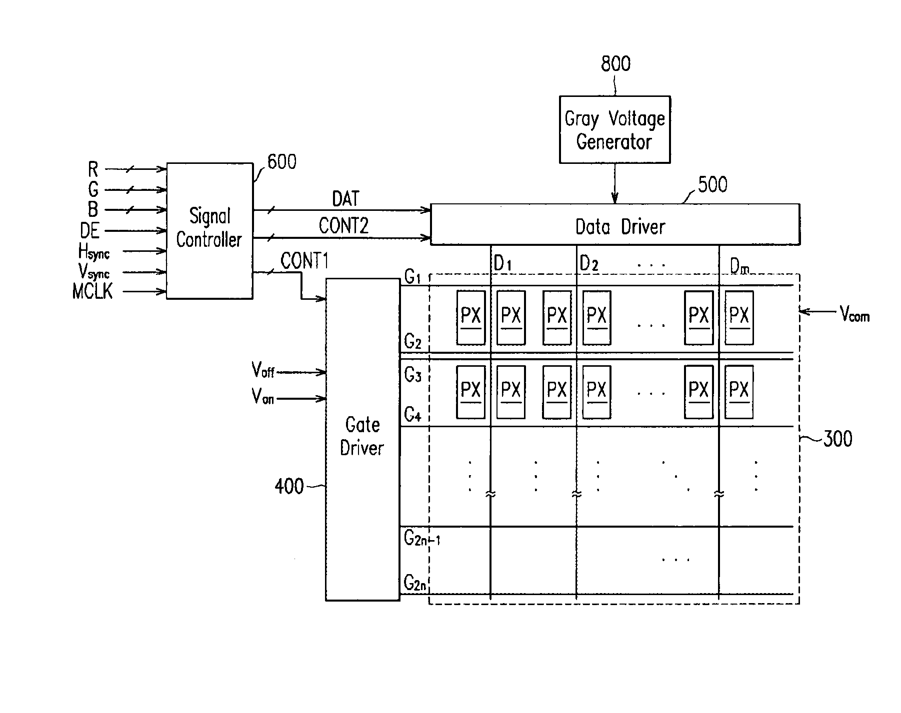
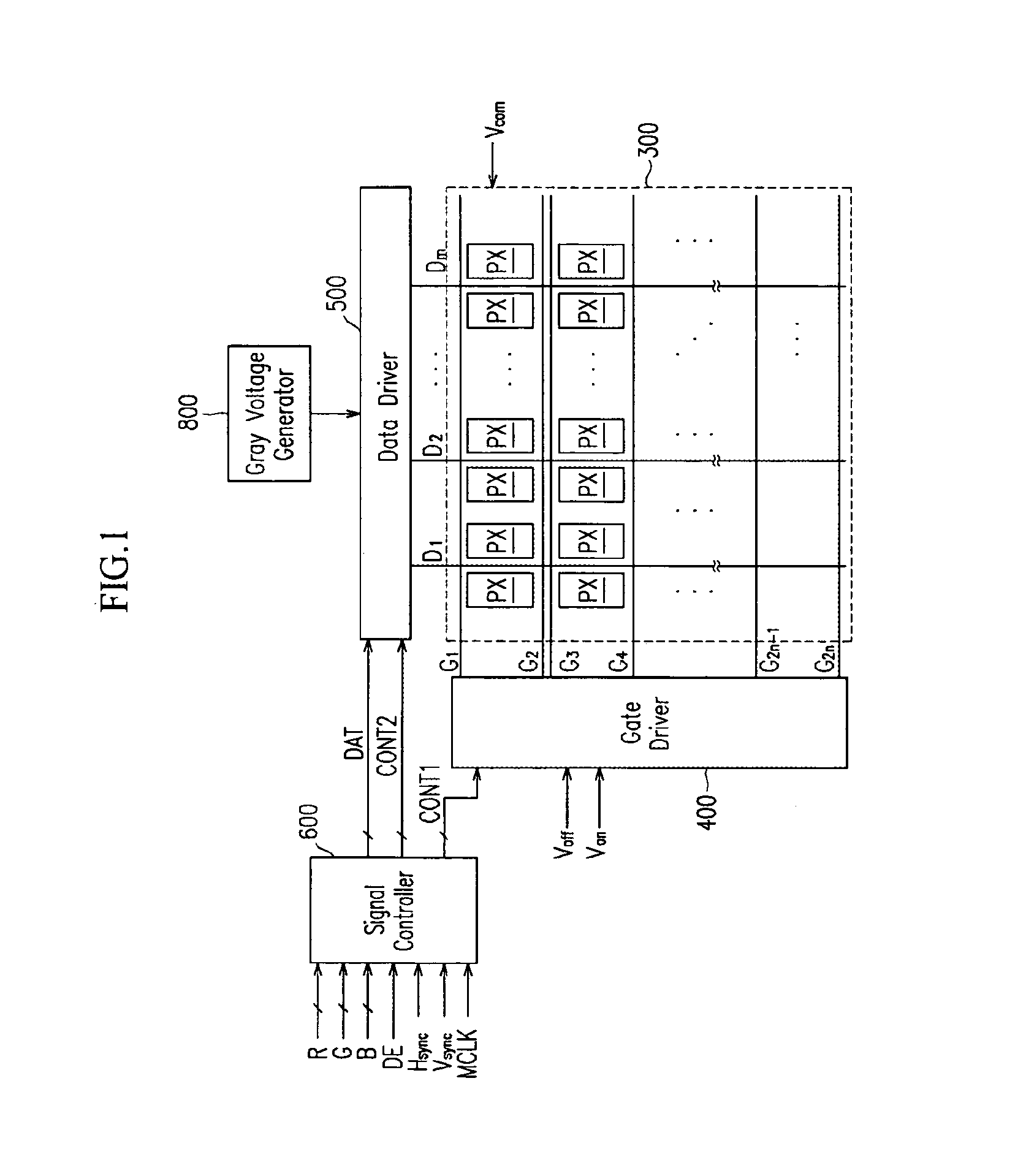
AI Technical Summary

Benefits of technology

This patent describes a display device with unique design features. The device includes a pixel matrix with rows and columns of pixels, each pixel having a switching element. The switching elements are positioned at the corners of each pixel. The device also has sets of gate lines and data lines connected to the pixels, which transmit signals to turn on the switching elements and carry data. The pixels are arranged in rows, with the first and second pixels in each row connected to different gate lines. The first and second pixels in each column have switching elements connected to the same data line, while the pixels in adjacent columns have switching elements connected to different data lines. This design allows for a 1×2 dot inversion, and a constant polarity of the data voltages transmitted by each data line. Additionally, a dummy line may be included to connect the switching elements of certain pixels in a different column to a nearby data line. Overall, this design enhances the display quality and image freshness of the display device.

Problems solved by technology

In particular, the number of the data driving IC chips is important since the data driving IC chips are much expensive than the gate driving IC chips.
However, the polarity inversion of the data voltages flowing in each data line may require complicated driving scheme and may cause signal delay.
Although the signal delay may be reduced by employing low resistivity metal, etc., it may complicate the manufacturing process and increase the production cost.
However, the column inversion is inferior to the dot inversion in terms of vertical crosstalk and vertical flickering, etc.

Method used


Image

  • Display device
  • Display device
  • Display device

Examples


Embodiment Construction

[0029]The present invention will now be described more fully hereinafter with reference to the accompanying drawings, in which preferred embodiments of the invention are shown. This invention may, however, be embodied in many different forms and should not be construed as limited to the embodiments set forth herein. Like numerals refer to like elements throughout.

[0030]In the drawings, the thickness of layers and regions are exaggerated for clarity. Like numerals refer to like elements throughout. It will be understood that when an element such as a layer, region or substrate is referred to as being “on” another element, it can be directly on the other element or intervening elements may also be present. In contrast, when an element is referred to as being “directly on” another element, there are no intervening elements present.

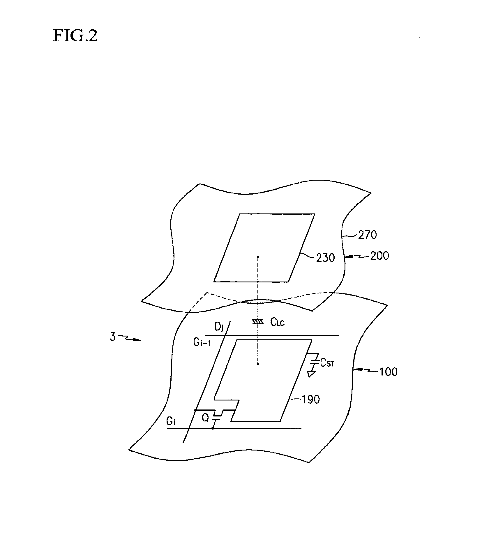
[0031]Then, liquid crystal displays as an example of display device according to embodiments of the present invention will be described with reference to the...


PUM

PropertyMeasurementUnit
luminanceaaaaaaaaaa
voltagesaaaaaaaaaa
voltageaaaaaaaaaa

Abstract

A display device includes a pixel matrix having pixel rows and pixel columns and including pixels having switching elements positioned alternately at a corner near an upper and a lower side of each pixel row and positioned alternately at a corner near an upper and a lower side of and alternately at a corner near a left and a right side of each pixel column; multiple pairs of gate lines transmitting a gate-on voltage; and multiple data lines transmitting data voltages, wherein each pair of gate lines are disposed at the upper and lower sides of each pixel row with the pixels in each row connected to the gate line positioned nearest the respective switching element, and each data line is disposed between adjacent pairs of pixel columns and connected to pairs of pixels where one pixel of the pair has a switching element positioned nearest the respective data line.

Description

CROSS-REFERENCE TO RELATED APPLICATION[0001]This application is a continuation application of U.S. patent application Ser. No. 11 / 109,607 filed on Apr. 18, 2005, which claims priority to Korean Patent Application No. 10-2004-0026753, filed on Apr. 19, 2004 in the Korean Intellectual Property Office (KIPO), and all the benefits accruing therefrom under 35 U.S.C. §119, the contents of the prior applications being herein incorporated by referenceBACKGROUND OF THE INVENTION[0002](a) Field of the Invention[0003]The present invention relates to a display device.[0004](b) Description of Related Art[0005]An active type display device such as an active matrix (AM) liquid crystal-display (LCD) and an active matrix organic light emitting display (OLED) includes a plurality of pixels arranged in a matrix and including switching elements and a plurality of signal lines such as gate lines and data lines for transmitting signals to the switching elements. The switching elements of the pixels selec...

Claims


Application Information

Patent Timeline
Patent Type & Authority Applications(United States)
IPC IPC(8): G09G3/36G02F1/1368G02F1/133G02F1/136G02F1/1362G09G3/20
CPCG09G3/36G02F1/136286G09G3/3611G09G3/3614G09G3/3648G09G2300/0426A47G19/025A47G2200/08A47G2200/106G09G3/3655G09G2300/0413G09G2300/0452G09G2310/08G09G2320/0209G09G2320/0247
Inventor KANG, NAM-SOOLEE, SEONG-YOUNGKIM, SUNG-MANMOON, SEUNG-HWAN
Owner SAMSUNG DISPLAY CO LTD
Features
  • R&D
  • Intellectual Property
  • Life Sciences
  • Materials
  • Tech Scout
  • Unparalleled Data Quality
  • Higher Quality Content
  • 60% Fewer Hallucinations
Learn More