Connector assembly

Active Publication Date: 2014-07-24
YAZAKI CORP
View PDF2 Cites 13 Cited by
  • Summary
  • Abstract
  • Description
  • Claims
  • Application Information

AI Technical Summary

Benefits of technology

The new connector assembly in this patent is designed to provide a strong connection between two connectors in multiple directions. This means that the connectors can be securely connected without any movement or loose connections, ensuring a tight and reliable connection. The design also utilizes a pressure contact between parts to eliminate any space between them, further strengthening the connection. Overall, this new connector assembly provides a more robust and effective connection between two devices.

Problems solved by technology

Thus, the connector assembly tends to have large vibrations thereof when vehicle vibrations propagate through a bracket.
However, because of no necessity of such a force in each direction within a plane intersecting with the engagement direction, the connector assembly is not structured to obtain a sufficient coupling force with an engagement force between a female connector and a male connector.

Method used


Image

  • Connector assembly
  • Connector assembly
  • Connector assembly

Examples


Embodiment Construction

[0030]A connector assembly according to an exemplary embodiment of the present invention will be described below with reference to the accompanying drawings. Note that, in the present embodiment, a shield connector is described as one example of the connector assembly. In the description of the following drawings, the same or similar portions are designated by the same or similar reference characters. However, drawings are schematic and the proportion of each dimension is different from a real one.

[0031]Accordingly, detailed dimensions should be determined in consideration of the following descriptions. Moreover, there is a difference between relationships or percentages of dimensions in drawings.

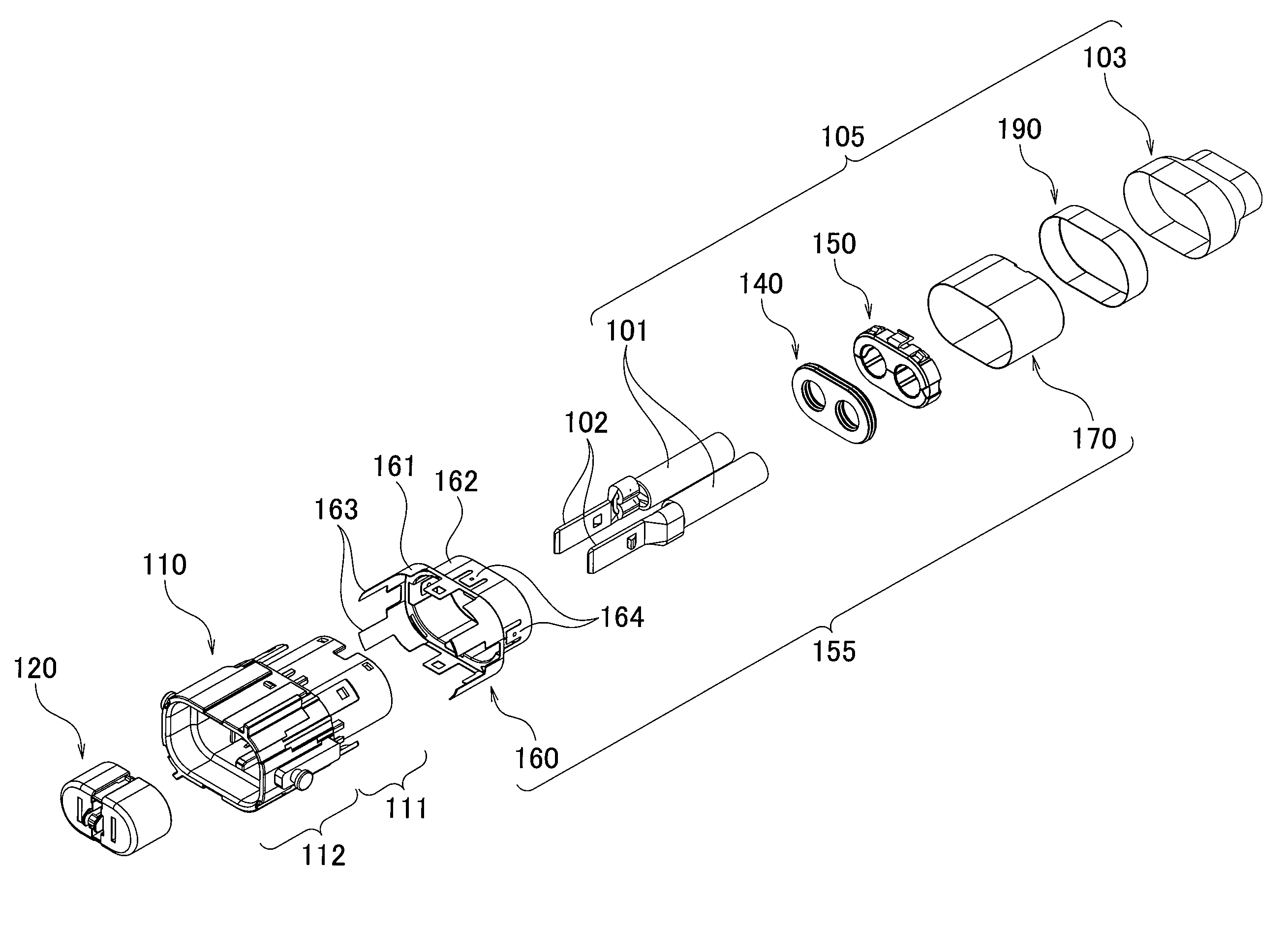
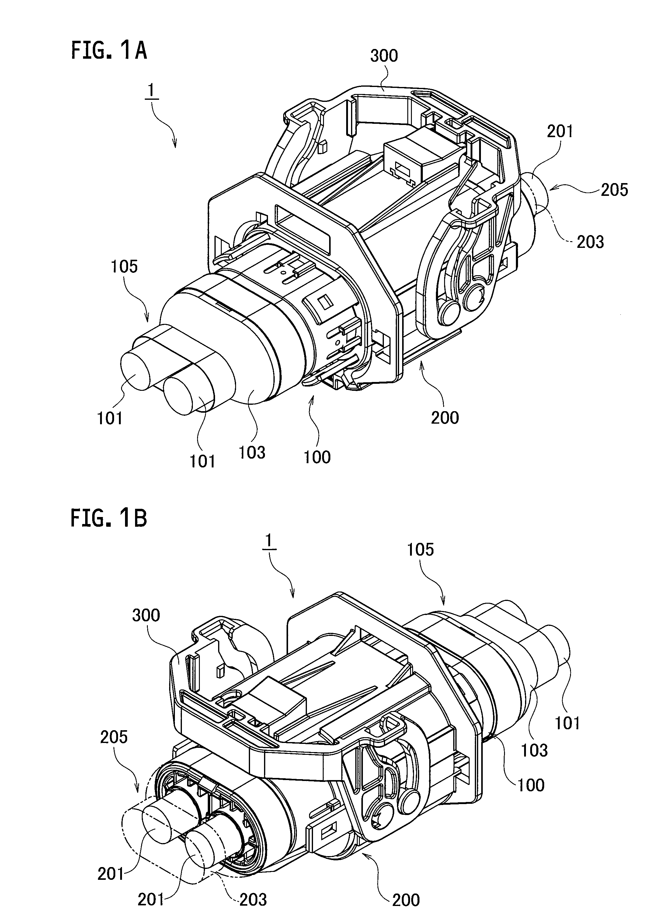
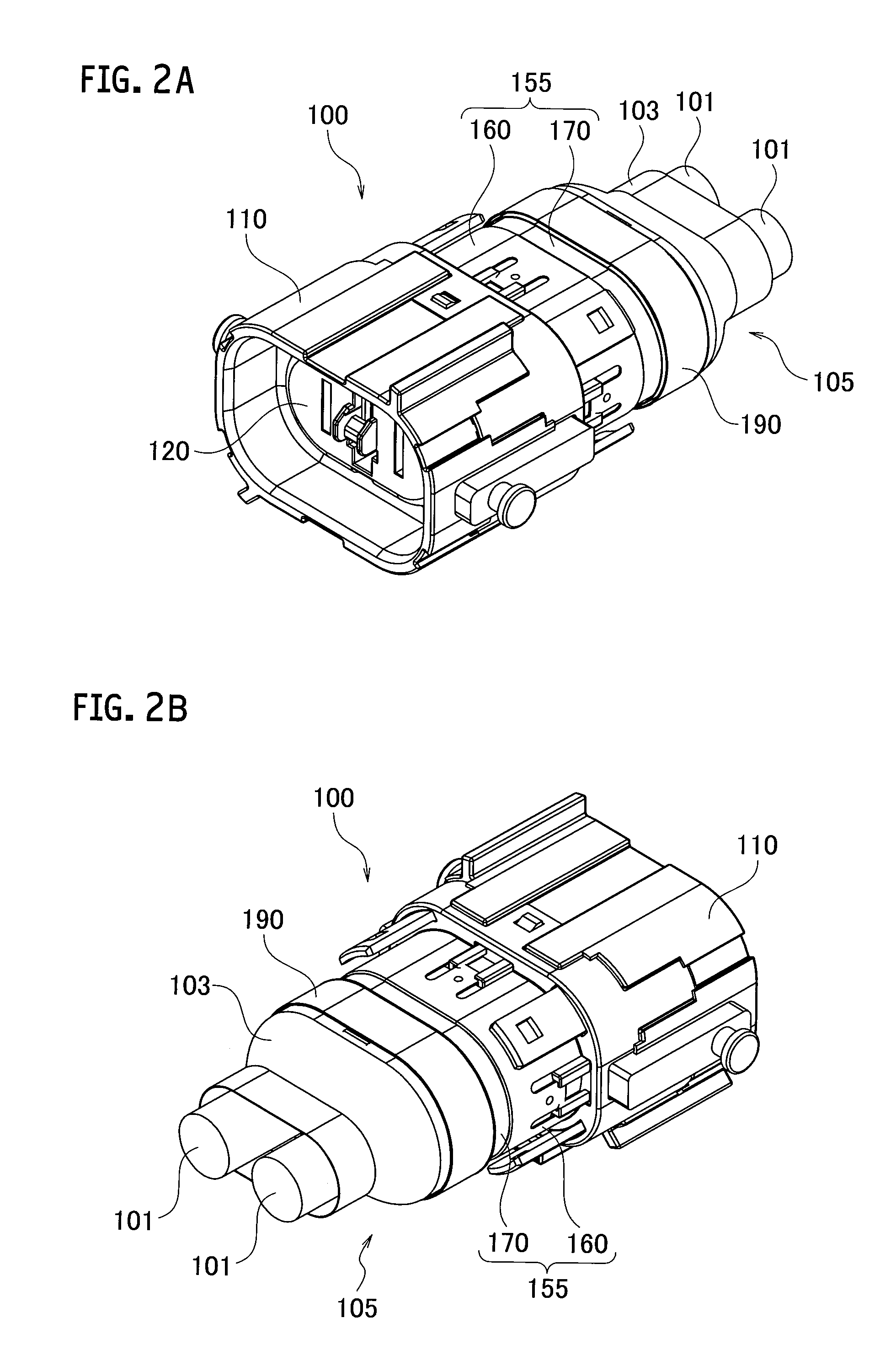
[0032]FIGS. 1A and 1B are perspective views of a shield connector according to the exemplary embodiment of the present invention. A shield connector 1 (connector assembly) shown in FIGS. 1A and 1B has a male connector 100 (second connector) and a female connector 200 (first connector) which...


PUM


Abstract

A fixing bracket inserted into a cassette type insertion section of a male housing extends to the outside from an opening formed in a hood of a female housing under a state where the male connector is engaged with a female connector. A side face, a bottom face and a side face of the cassette type insertion section extending in the insertion direction of the male housing into the female housing come into face contact with inner faces provided for the hood, respectively.

Description

CROSS REFERENCE TO RELATED APPLICATION[0001]This is a continuation application based on PCT application No. PCT / JP2012 / 006151 filed on Sep. 26, 2012, which claims the benefit of priority from Japanese Patent Application No. 2011-210874 filed on Sep. 27, 2011, the entire contents of which are incorporated by reference herein.BACKGROUND OF THE INVENTION[0002]1. Field of the Invention[0003]The present invention relates to a connector assembly that engages a second connector with a first connector by inserting a second housing of the second connector into a first housing of the first connector and connects a terminal of the second housing to a terminal in the first housing.[0004]2. Description of the Related Art[0005]There has conventionally been known a connector assembly that engages a second connector with a first connector by inserting a second housing of the second connector into a first housing of the first connector and that connects a terminal of the second housing to a terminal...

Claims


Application Information

Patent Timeline
IPC IPC(8): H01R13/62
CPCH01R13/62H01R13/533H01R13/62938H01R13/639H01R2201/26
Inventor KATO, HAJIMESHINBA, HIROSHI
Owner YAZAKI CORP
Why Eureka
Try Eureka