

Enhanced Backup Ring Features for Metal Face Seal in Roller Cone Drill Bits
- Summary
- Abstract
- Description
- Claims
- Application Information
AI Technical Summary
Benefits of technology
Problems solved by technology
Method used
Image

Examples
Embodiment Construction
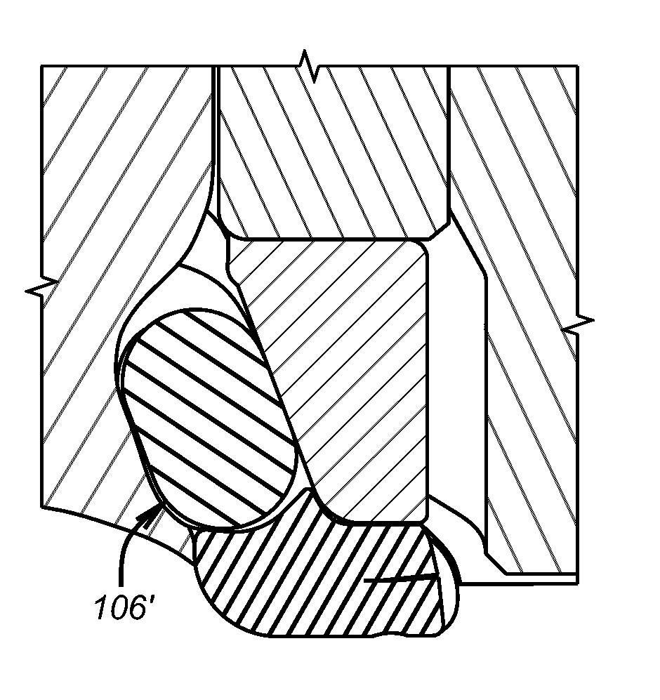
[0034]FIG. 5 shows the backup ring 100 of the present invention with an outer edge 102 that has a curved recess 104. When assembled to a roller cone face seal assembly 106 as previously described opposing forces 108 and 110 are represented by arrows. Assembly causes the recess 104 to get smaller than its relaxed uninstalled shape. The hardness of the ring 100 is increased as compared to the previously discussed prior embodiment where the hardness was 40-45 durometer (Shore A). The increase in hardness, modulus or density addresses the issue of cracking or pieces coming off from contact with the abrasives in well fluids notably drilling mud. However, the increase in hardness or density also increases the reaction forces to the forces represented by arrows 108 and 110. For that reason some material is removed from edge 102 that creates cantilevered components 112 and 114 that under loading from assembly and then during operation can flex toward each other to compensate for the increas...
PUM
 Abstract
Description
Claims
Application Information