Eureka AIR delivers breakthrough ideas for toughest innovation challenges, trusted by R&D personnel around the world.

Automatic alignment of an imager

Inactive Publication Date: 2014-08-28
OPTOVUE
View PDF3 Cites 15 Cited by
  • Summary
  • Abstract
  • Description
  • Claims
  • Application Information

AI Technical Summary

Benefits of technology

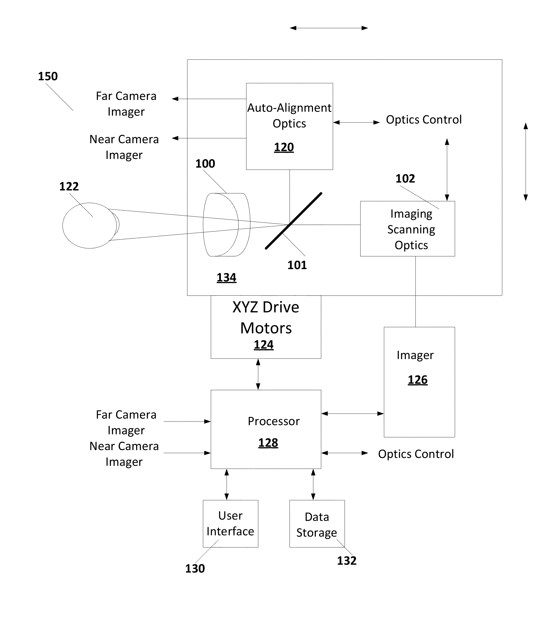
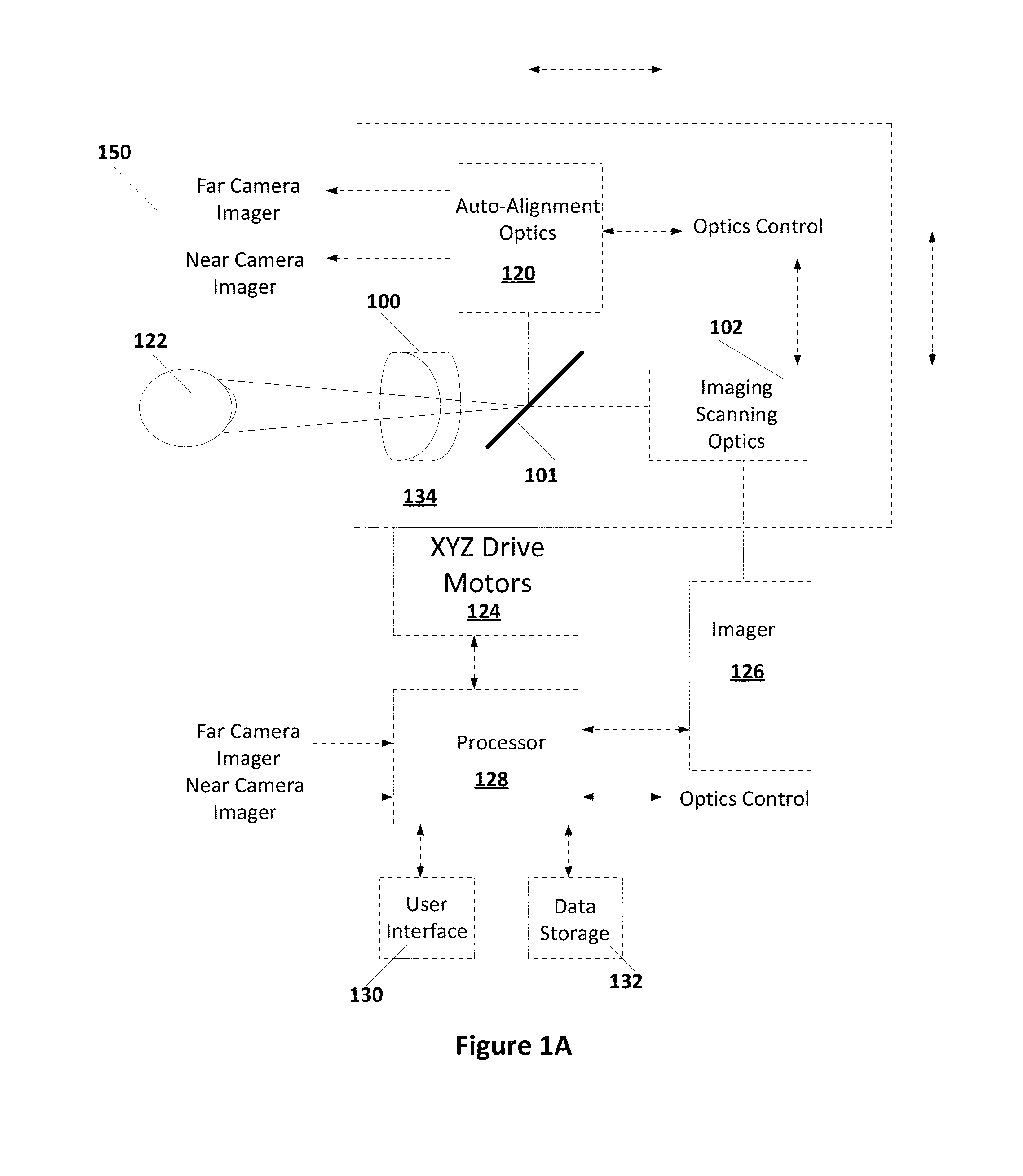
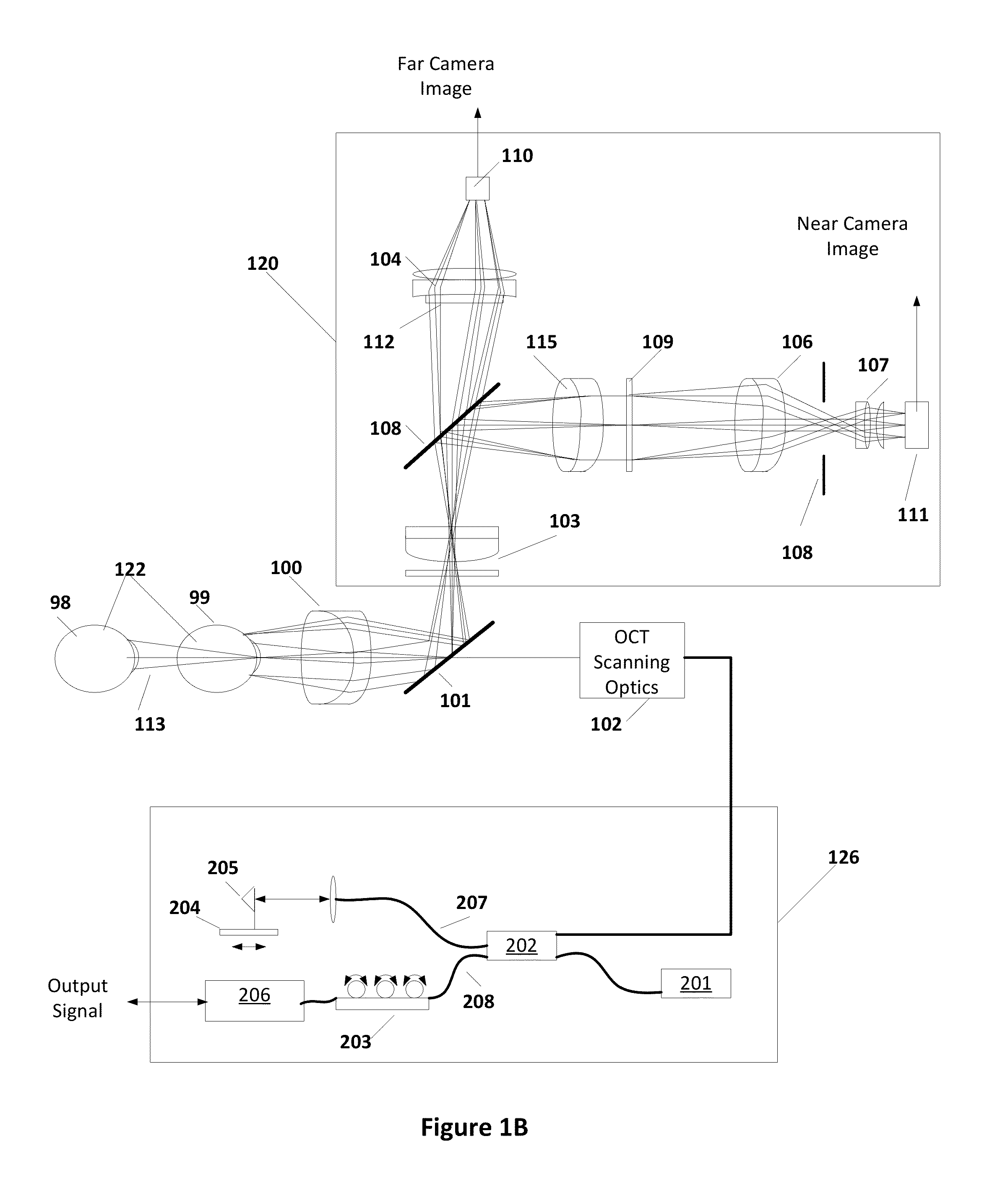
The present invention provides an automatic alignment system for an image sensor. The system includes an adjustment stage, auto-alignment optics, imaging scanning optics, an imager, and a processor. The processor receives an image of the object and adjusts the adjustment stage to align the optics with the scanning optics. This allows for easier and quicker alignment of the image sensor system, improving efficiency and accuracy.

Problems solved by technology

Often the inexperience of the operators results in less effective OCT imagery and lengthy examination times, which limits the use of such instruments.
Such alignment and optimization requires the operator to perform multiple alignment and optimization steps in a very short time, especially before the patient is fatigued by the examination.

Method used


Image

  • Automatic alignment of an imager
  • Automatic alignment of an imager
  • Automatic alignment of an imager

Examples


Embodiment Construction

[0018]In the following description, specific details are set forth describing some embodiments of the present invention. It will be apparent, however, to one skilled in the art that some embodiments may be practiced without some or all of these specific details. The specific embodiments disclosed herein are meant to be illustrative but not limiting. One skilled in the art may realize other elements that, although not specifically described here, are within the scope and the spirit of this disclosure.

[0019]This description and the accompanying drawings that illustrate inventive aspects and embodiments should not be taken as limiting—the claims define the protected invention. Various changes may be made without departing from the spirit and scope of this description and the claims. In some instances, well-known structures and techniques have not been shown or described in detail in order not to obscure the invention.

[0020]The embodiments described below are provided in order to demons...


PUM


Abstract

Embodiments of automatically aligning imager are presented. In accordance with some embodiments, an imaging system includes an adjustment stage; an auto-alignment optics mounted on the adjustment stage and coupled to image an object, the auto-alignment optics including at least one video camera providing an image of the object; imaging scanning optics mounted on the adjustment stage and coupled to scan the object; an imager coupled to the imaging scanning optics; and a processor coupled to the adjustment stage and the auto-alignment optics, the processor executing instructions to receive the image of the object and adjust the adjustment stage to align the optics with the imaging scanning optics.

Description

RELATED APPLICATIONS[0001]The present application claims priority to U.S. Provisional Application No. 61 / 770,289, filed on Feb. 27, 2013, which is herein incorporated by reference in its entirety.BACKGROUND[0002]1. Technical Field[0003]Embodiments of the present invention are related to imaging and, in particular, to an imager that operates automatically or semi-automatically to generate an image.[0004]2. Discussion of Related Art[0005]Imaging technologies continue to play a large role in various evaluation techniques. Optical Coherence Tomography (OCT), for example, has evolved from an ophthalmic imaging device, which was adopted by a majority of retina specialists and major institutes over 10 years ago, to a daily clinical tool used in many ophthalmologist and optometrist offices. A majority of patients come to the office with some symptom of eye conditions that can be examined by the OCT imager. The volume of patients examined by an OCT technique has skyrocketed in recent years. ...

Claims


Application Information

Patent Timeline
IPC IPC(8): A61B3/10
CPCA61B3/102A61B3/152
Inventor WEI, JAYCUI, JINGHUANG, TAOSTANESCU, DRAGOS
Owner OPTOVUE
Why Eureka
Eureka Blog
Learn More