Vehicle blind spot monitoring system

a technology for monitoring systems and vehicles, applied in television systems, identification means, instruments, etc., can solve problems such as visual or audible warning, difficulty in seeing obstacles, and less useful at night and under adverse weather conditions, and achieve the effect of enhancing driver safety

Inactive Publication Date: 2004-05-18
FORD GLOBAL TECH LLC
View PDF10 Cites 426 Cited by
  • Summary
  • Abstract
  • Description
  • Claims
  • Application Information

AI Technical Summary

Benefits of technology

It is, therefore, an object of the invention to provide an improved and reliable vehicle blind spot monitoring system. Another object of the invention is to enhance driver safety by providing a visual image of the vehicle's blind spot. Additionally, the new technique should be capable of replacing a conventional side view mirrors.
The present invention thus achieves an improved vehicle blind spot monitoring system. The present invention is advantageous in that it enhances driver safety by providing an image of the vehicle's blind spots.

Problems solved by technology

A continuing problem that presents itself to operators of automotive vehicles is the difficulty in seeing obstacles near the vehicle but in a location that is difficult to observe from the driver's seat.
These right-side and left-side blind spots are a source of numerous accidents when a driver makes a turn or a lane change and does not see another vehicle in the blind spot.
Mirrors provide the operator with some information regarding the presence of obstacles in certain of a vehicle's blind spots, but they are less useful at night and under adverse weather conditions.
Unfortunately, these systems only provide a visual or audible warning, and do not allow the vehicle operator to actually see what is in the vehicle's blind spot.
The disadvantages associated with these conventional blind spot monitoring techniques have made it apparent that a new technique for monitoring a vehicle's blind spots is needed.

Method used


Image

  • Vehicle blind spot monitoring system
  • Vehicle blind spot monitoring system

Examples


Embodiment Construction

]

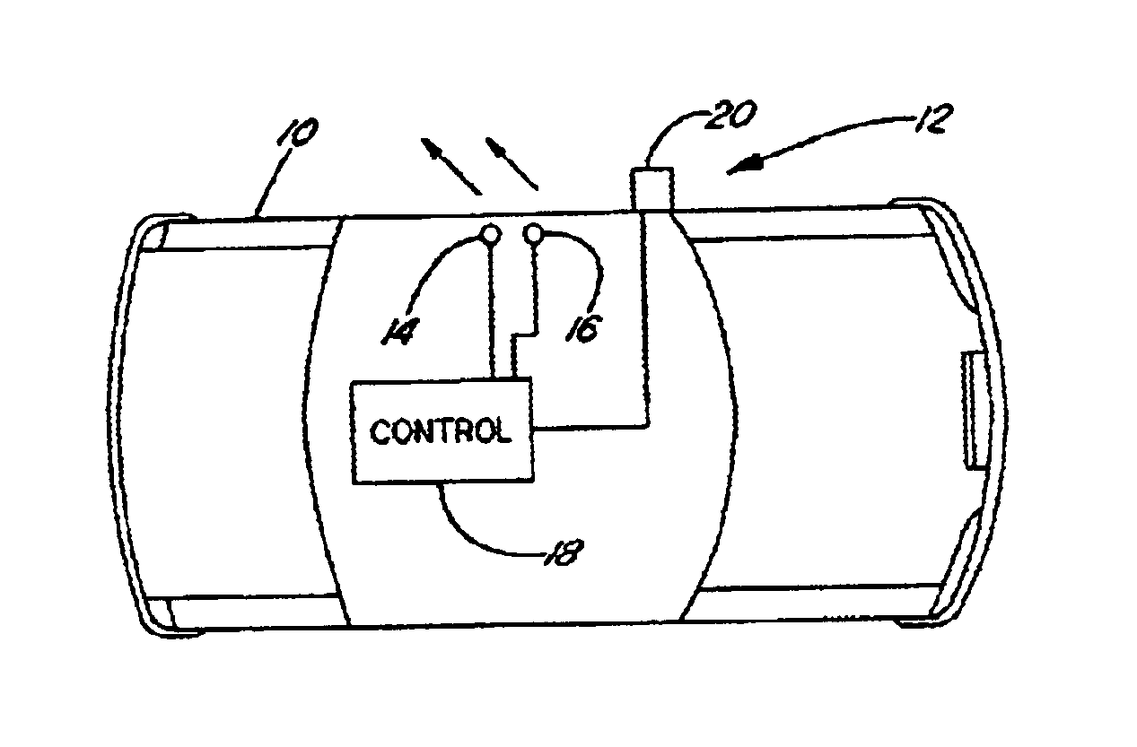
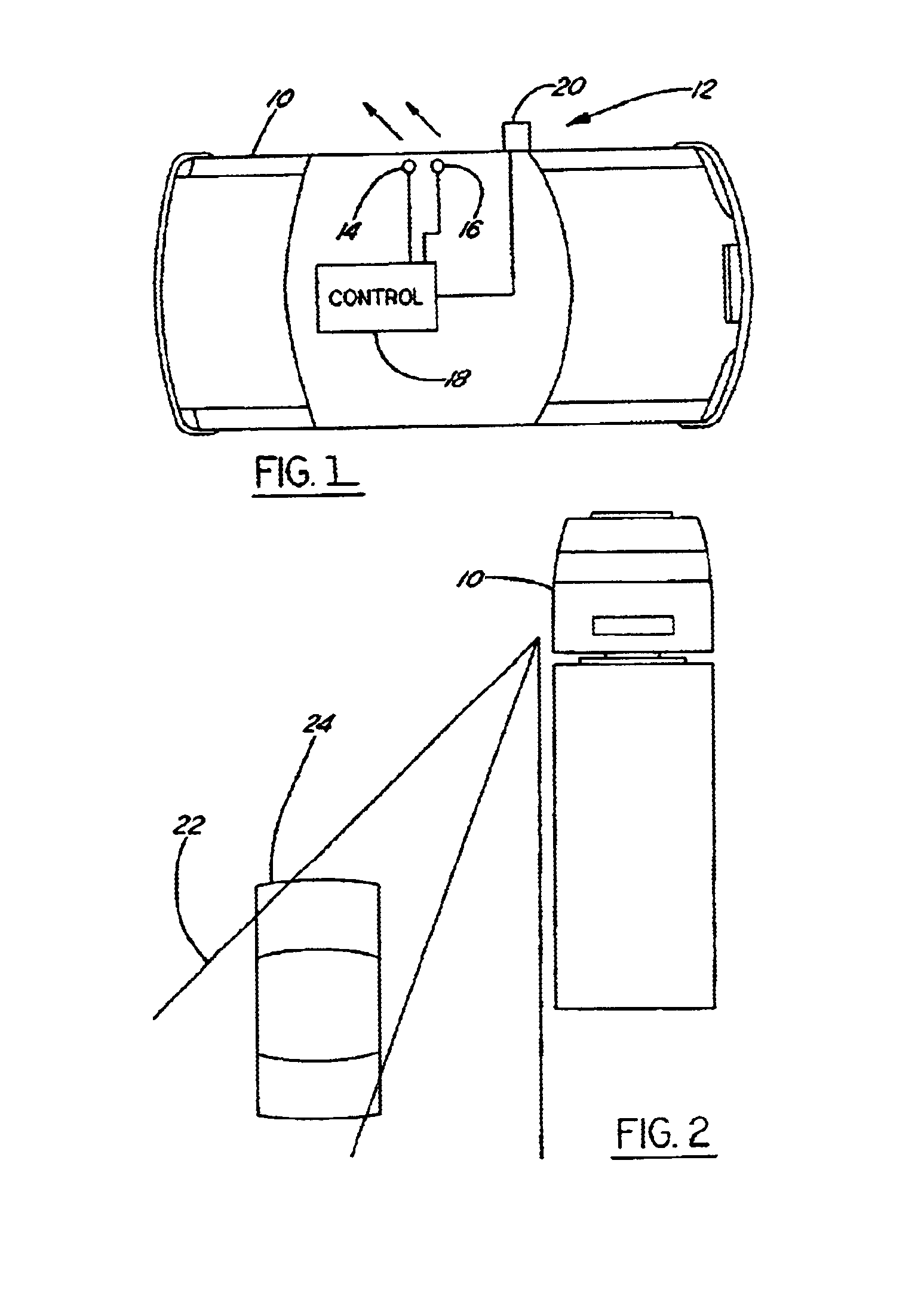
In the following figures, the same reference numerals will be used to identify identical components in the various views. Both figures represent the driver side of the vehicle only (the passenger side is the mirror image of the driver side). The present invention is illustrated with respect to a vehicle blind spots monitoring system, particularly suited for the automotive field. However, the present invention is applicable to various other uses that may require vehicle blind spots monitoring systems.

Referring to FIG. 1, a block diagram of a vehicle 10 having a vehicle blind spot monitoring system 12 in accordance with one embodiment of the present invention is illustrated. Vehicle blind spot monitoring system 12 includes a pair of stereo cameras 14, 16, a controller 18 having a plurality of computer algorithms, and a display 20.

While driving a vehicle, there are blind spots, i.e. an area not covered by looking at side mirrors, rear view mirrors, forward vision or peripheral. In man...


PUM


Abstract

A blind spot monitoring system for a vehicle includes two pairs of stereo cameras, two displays and a controller. The stereo cameras monitor vehicle blind spots and generate a corresponding pair of digital signals. The display shows a rearward vehicle view and may replace, or work in tandem with, a side view mirror. The controller is located in the vehicle and receives two pairs of digital signals. The controller includes control logic operative to analyze a stereopsis effect between each pair of stereo cameras and the optical flow over time to control the displays. The displays will show an expanded rearward view when a hazard is detected in the vehicle blind spot and show a normal rearward view when no hazard is detected in the vehicle blind spot.

Description

BACKGROUND OF INVENTION1. Technical FieldThe present invention relates generally to automotive control systems, and more particularly, to a vehicle blind spot monitoring system.2. Background ArtA continuing problem that presents itself to operators of automotive vehicles is the difficulty in seeing obstacles near the vehicle but in a location that is difficult to observe from the driver's seat. Such regions are commonly referred to as "blind spots". For example, the angles between 90.degree. and 170.degree. from the forward direction of a vehicle (i.e., to the right and to the left of the vehicle and slightly behind the operator thereof) are common blind spots. These right-side and left-side blind spots are a source of numerous accidents when a driver makes a turn or a lane change and does not see another vehicle in the blind spot. Another common blind spot is the rear of a vehicle when backing up.The most common solution to the problem of blind spots has been to use mirrors to aid ...

Claims


Application Information

Patent Timeline
Patent Type & Authority Patents(United States)
IPC IPC(8): B60R1/00
CPCB60R1/00B60R2300/101B60R2300/105B60R2300/107B60R2300/30B60R2300/8026B60R2300/8066
Inventor SAMMAN, AMER MOHAMMEDSMITH, GREGORY HUGHRANKIN, II, JAMES STEWARTEBENSTEIN, SAMUEL EDWARD
Owner FORD GLOBAL TECH LLC
Why Eureka
Try Eureka