Image monitoring and display from unmanned vehicle

a technology for monitoring and displaying images, applied in the field of image monitoring and display from a vehicle, can solve the problems of difficult accuracy of attitude and control adjustments, reduced object size, and pilot's ability, and achieve the effects of extending the range of the uav's operational area, facilitating suitable line-of-sight (loss) signal transmission, and boosting signal quality

Inactive Publication Date: 2014-11-06
CRANE COHASSET HLDG
View PDF20 Cites 76 Cited by
  • Summary
  • Abstract
  • Description
  • Claims
  • Application Information

AI Technical Summary

Benefits of technology

[0013]The expanded perspective, wrap-around view, image capture and monitoring system, which can be in both vertical and horizontal views, for remote piloting of UAVs is intended to counteract the limitations of the traditional single camera and monitor FPV combination for UAVs by providing the pilot or operator thereof with a wider, yet substantially undistorted optical perspective that is more in line with the way a human normally sees the environment that encircles him. By enhancing peripheral vision and affording the pilot or operator (or an individual monitoring the craft's actions if it is being flown autonomously) the ability to see what is surrounding the aircraft in all directions, more accurate control input decisions can be made with vastly improved situational awareness and obstacle avoidance capabilities. The cumulative effect further makes the craft safer and improves capability for aerial surveillance, aerial inspection, aerial mapping, transport and lifting of materiel, aerial photography or videography, and other remotely controlled UAV applications.
[0059]The complete system and its operation, from image capture, through transmission, to monitoring, would be designed to accomplish minimal delay or latency throughout the signal chain to give the pilot or operator information in as close to real time as technically feasible.
[0061]The image displayed on the monitoring portion of the system can be augmented or even replaced by computer generated 3D map imagery linked to a navigational system such as GPS or a Real Time Kinematic System if desired. And although the displayed image may be generated synthetically, the benefits of the wrap-around view would still be present in that it provides the pilot or operator(s) with wide perspective, visual cues and increased situational awareness for accurate control input and craft maneuverability.
[0062]For example, if a UAV is being operated in an environment of reduced or even zero visibility, such as in fog or during fire fighting operations where very thick smoke is present, the wrap-around computer generated, augmented view of surrounding terrain or obstacles will allow the pilot or operator the ability to maneuver the craft effectively and safely despite his or her inability to see any clear image using a conventional visual spectrum video feed.
[0064]In one embodiment, the airborne component (Stages 1 and 2) of the expanded perspective, wrap-around view, image capture and monitoring system installation, in any of its variants, can be placed within a protective housing, chamber or other suitable structure that safeguards and protects the components such as the lenses from weather elements, from shock in the event of a crash, hostile weapons attacks, or if it allows for aerodynamic benefits. Various filters may also be provided on the cameras, and in another embodiment, some or all of the cameras or sensors may be contained in a dedicated housing or container to afford the necessary protection.
[0065]Transmission repeaters or signal amplifiers can be added to the system and placed in a location or locations which are considered to improve or boost signal quality or extend the range of the UAV's operational area. As on example only, if a craft is flown on one side of a mountain range, with the pilot or operator's monitoring station situated on the other side of a mountain range in a position that does not facilitate a suitable line-of-sight (LOS) signal transmission, a repeater and / or an amplifying device can be placed at a point of high elevation atop the mountain range to aid in the quality and strength of the signal that is being transmitted and received.

Problems solved by technology

When using a single lens, conventionally-configured camera and monitor combination, the relatively narrow perspective that is created may hinder a pilot's ability to ascertain an object's true location and proximity to the UAV due to a lack of ambient visual cues, making accurate attitude and control adjustments more difficult.
The problem with using an extreme wide angle lens is that, because of it's unnaturally exaggerated wide perspective and accompanying increased spherical distortion, objects appear diminished in size and an observer's perception of movement and speed is inaccurate, making the precise maneuvering of the craft difficult.
This effect is somewhat analogous to the configuration of the right side view mirror in most automobiles, namely, objects are closer than they appear, with accurate distance determinations therefore difficult to make.

Method used


Image

  • Image monitoring and display from unmanned vehicle
  • Image monitoring and display from unmanned vehicle
  • Image monitoring and display from unmanned vehicle

Examples


Embodiment Construction

[0087]Reference is now made to the accompanying drawings which show various embodiments of the invention. The drawings are intended to illustrate some of the embodiments, but certainly not all, which can be configured and constructed in accordance with the invention.

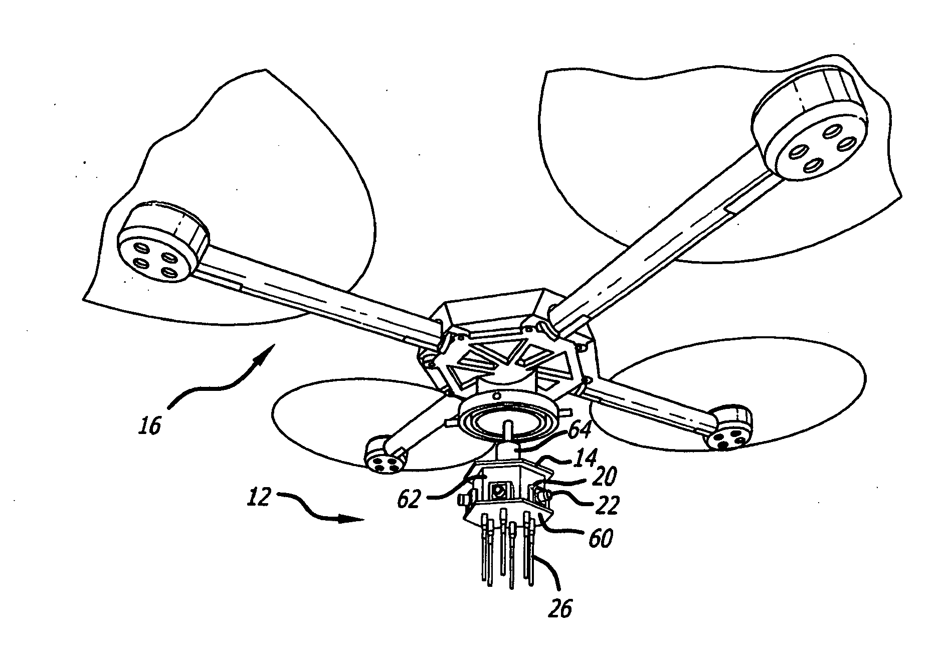
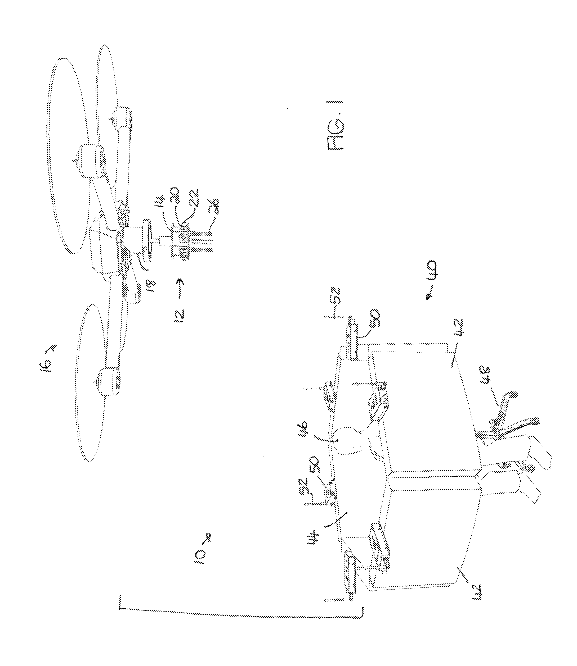
[0088]FIG. 1 of the drawings illustrates an image monitoring and display system 10 of the invention. It is noted that the monitoring and display is not limited to conventional video in the visual spectrum, but can also utilize infrared, thermal, radiation, or other sensors and display mechanisms. Therefore, any reference herein to visual spectrum image and display should also be understood to encompass all other types of sensing and their respective forms of display.

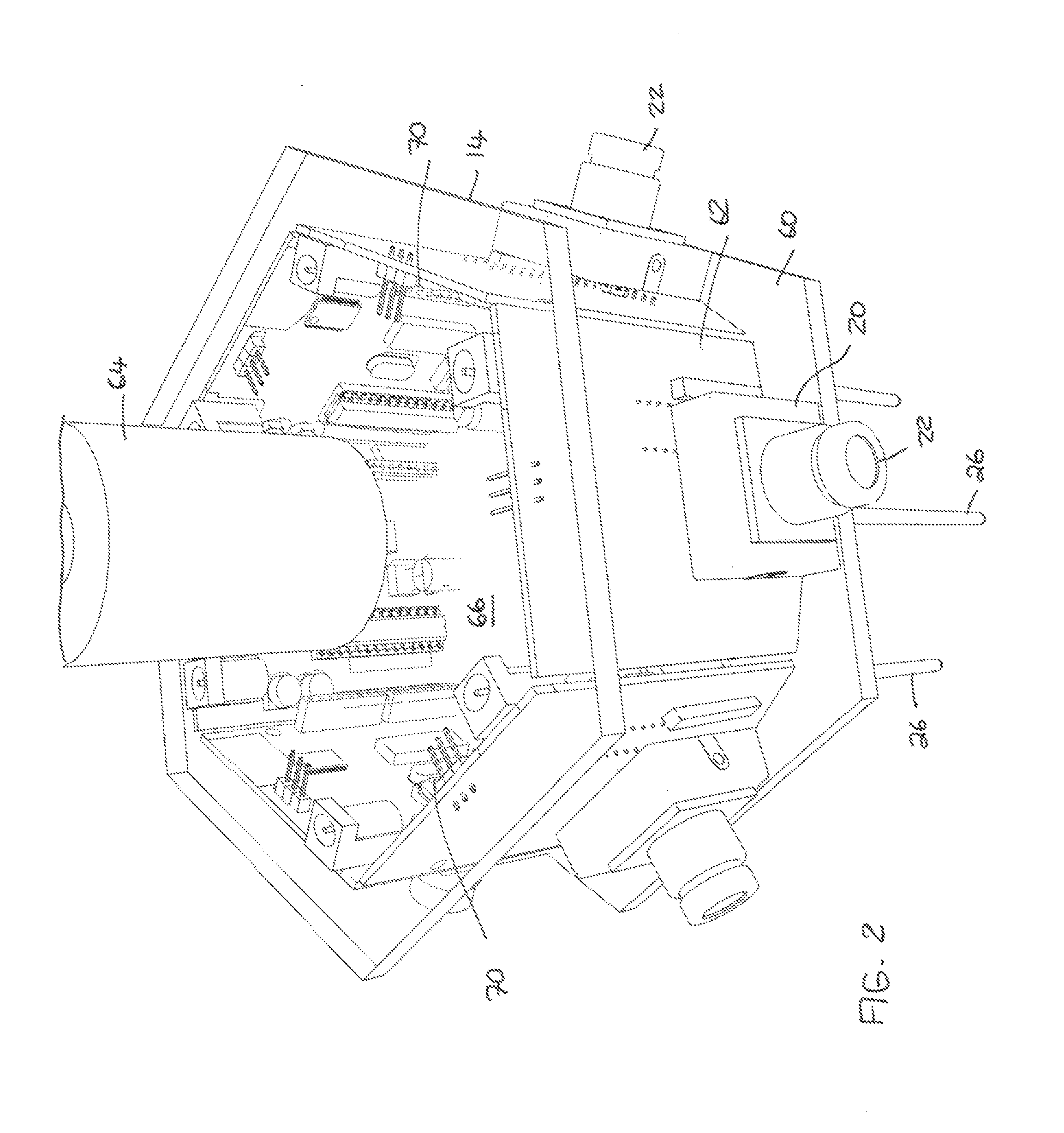
[0089]The monitoring and display system 10 comprises and camera array 12 mounted on a frame 14, which is attached to the underside of an unmanned aerial vehicle 16. One type of aerial vehicle 16 is shown in FIG. 1, but many types may be used. These include ma...


PUM


Abstract

An image capture and display system comprises an image capture array positioned on a vehicle, the image capture array comprising a plurality of image sensing members. At least one transmitter is provided for transmitting images from the image sensing members. The system also includes a monitor display array positioned remotely from the image capture array. The monitor display array comprises a display monitor for and corresponding to each image sensing member, and a receiver for receiving the images corresponding to each transmitter.

Description

CROSS REFERENCE TO RELATED APPLICATIONS[0001]This application is a continuation-in-part application of U.S. patent application Ser. No. 13 / 847,161 filed Mar. 19, 2013, which claims the benefit of U.S. Provisional Patent Application No. 61 / 685,539 filed Mar. 20, 2012, the contents of both of which are incorporated by reference herein in their entirety.FIELD AND BACKGROUND OF THE INVENTION[0002]This invention relates to an image monitoring and display from a vehicle, typically an unmanned vehicle, but also capable of use on a manned vehicle. More particularly, the invention relates to a system of sensors mounted on a vehicle, whether manned or unmanned, a display system, and transmission and reception mechanisms associated with the sensors and display system respectively whereby images or information captured by the sensors can be viewed on the display system. There may be a single or multiple display systems.[0003]In one preferred form, the invention is for an expanded perspective, w...

Claims


Application Information

Patent Timeline
Patent Type & Authority Applications(United States)
IPC IPC(8): H04N7/18H04N5/232H04N5/30H04N5/33
CPCH04N7/185H04N5/33H04N5/23238H04N5/30H04N23/661H04N23/698H04N23/63H04N23/90B64U2101/30B64U2201/20B64C39/024B64D47/08H04N7/181
Inventor WAGREICH, DAVID
Owner CRANE COHASSET HLDG
Why Eureka
Try Eureka