Control system for rotorcraft for preventing the vortex ring state

a control system and rotorcraft technology, applied in the direction of aircraft navigation control, vertical landing/take-off aircraft, transportation and packaging, etc., can solve the problems of substantial recirculation and turbulence, the assumption of momentum theory beginning to break down, and the expansion of the slipstream is very larg

Inactive Publication Date: 2005-01-06
BELL HELICOPTER TEXTRON INC
View PDF6 Cites 7 Cited by
  • Summary
  • Abstract
  • Description
  • Claims
  • Application Information

AI Technical Summary

Benefits of technology

[0019]FIG. 2 is a perspective view of a helicopter having a flight control system for preventing the adverse effects of the vortex ring state according to the present invention;
[0020]FIG. 3A is a plan view of a tiltrotor aircraft having a flight control system for preventing the adverse effects of the vortex ring state according to the present invention in an airplane mode;
[0021]FIG. 3B is a perspective view of another tiltrotor aircraft having a flight control system for preventing the adverse effects of the vortex ring state according to the present invention in a helicopter mode;
[0022]FIG. 4 is a perspective view of a Quad tiltrotor aircraft having a flight control system for preventing the adverse effects of the vortex ring state according to the present invention in the airplane mode;

Problems solved by technology

However, when a rotorcraft begins to descend, the assumptions of the momentum theory begin to break down.
For low rates of descent, the expansion of the slipstream is very large, and substantial recirculation and turbulence are generated.
At high rates of descent and low horizontal airspeeds, the low wake skew angle and high rotor vertical velocity cause the rotor to re-ingest its wake.
Operation within these boundaries is highly unsteady and can lead to temporary, and sometimes catastrophic, loss of control.

Method used


Image

  • Control system for rotorcraft for preventing the vortex ring state
  • Control system for rotorcraft for preventing the vortex ring state
  • Control system for rotorcraft for preventing the vortex ring state

Examples


Embodiment Construction

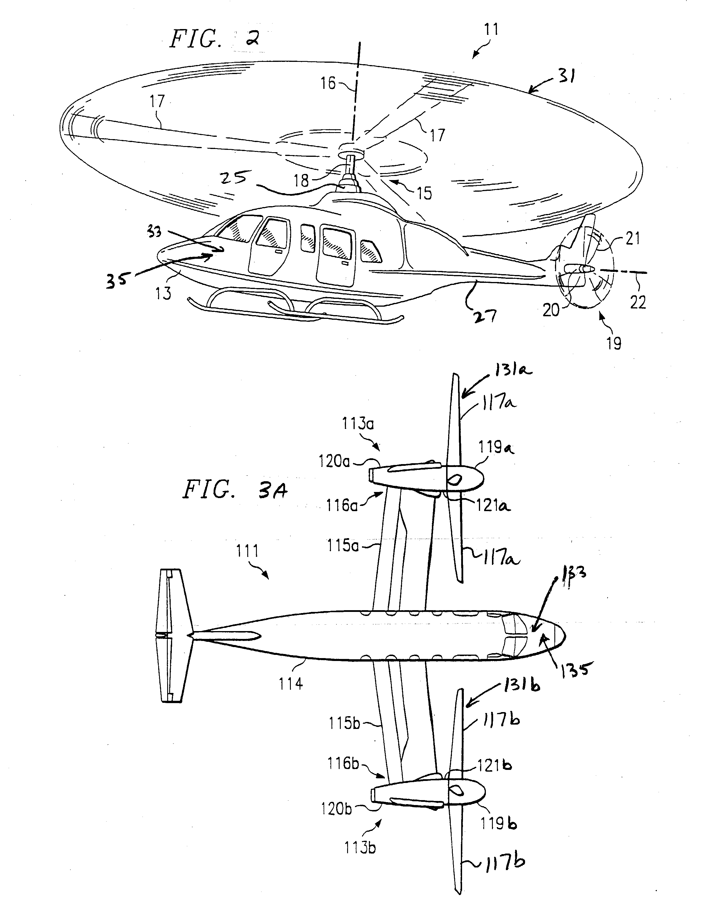
[0025] The present invention represents a means of preventing or delaying the vortex ring state for any type of rotorcraft. Although the present invention may be described with reference to tiltrotor aircraft, such as those depicted in FIGS. 3A and 3B, it should be understood that the present invention may be used on other types of rotorcraft, such as helicopters, as depicted in FIG. 2, tilt wing aircraft, and tail sitter aircraft. It will also be appreciated that both the civilian and military tiltrotor aircraft described herein may have two wing assemblies and two tiltrotor assemblies, or may be “Quad” type tiltrotor aircraft having four wing members and four tiltrotor assemblies, as depicted in FIG. 4. In addition, it will be appreciated that the present invention is particularly well suited for rotorcraft that are unmanned aerial vehicles.

[0026] Referring to FIG. 2 in the drawings, a helicopter 11 having a flight control system for preventing the vortex ring state according to ...


PUM


Abstract

A flight control system for a rotorcraft to prevent the adverse effects of the vortex ring state is disclosed. In the flight control system of the present invention, selected control inputs are sent the rotorcraft prior to the onset of the vortex ring state. In the preferred embodiment, the control inputs are transient, do not require input from the pilot, and do not affect the flight path of the rotorcraft.

Description

BACKGROUND [0001] 1. Field of the Invention [0002] The present invention relates to flight control systems for rotorcraft. [0003] 2. Description of Related Art [0004] There are many different types of rotorcraft, including: helicopters, tandem rotor helicopters, tiltrotor aircraft, four-rotor tiltrotor aircraft, tilt wing aircraft, and tail sitter aircraft. In all of these rotorcraft, thrust and / or lift is generated by air flowing through a rotor disk formed by rotating rotor blades. [0005] There are three basic flow states for the air flow through the rotor disk of a rotorcraft: (1) the normal working state; (2) the windmill-brake state; and (3) the vortex ring state. These three flow states are typically described in terms of hover induced velocity, which is determined from the momentum theory. The basic premise of momentum theory is that a definite wake field exists far downstream of a hovering rotor. However, when a rotorcraft begins to descend, the assumptions of the momentum t...

Claims


Application Information

Patent Timeline
Patent Type & Authority Applications(United States)
IPC IPC(8): B64C27/28B64C27/57B64C29/00
CPCB64C27/28B64C29/0033B64C27/57
Inventor KISOR, RONALD L.
Owner BELL HELICOPTER TEXTRON INC
Why Eureka
Try Eureka