Vehicle underfloor structure

a technology of vehicle underfloor and vehicle body, which is applied in the direction of propulsion parts, transportation and packaging, electric propulsion mounting, etc., can solve the problems of increasing achieve the effect of reducing the weight of the vehicle, improving the assemblability of the fuel tank, and reducing the impact of collision load

Inactive Publication Date: 2019-04-16
TOYOTA JIDOSHA KK
View PDF9 Cites 7 Cited by
  • Summary
  • Abstract
  • Description
  • Claims
  • Application Information

AI Technical Summary

Benefits of technology

[0005]Thus, an object of the present disclosure is to provide a vehicle underfloor structure that can achieve both control of input of collision load to a fuel tank and lightening of the weight of a vehicle.

Problems solved by technology

However, when the fuel tank is disposed at the vehicle body rear side of the battery pack, a strong member must be disposed at the vehicle body rear side of the fuel tank in order for collision load to not be inputted to the fuel tank at the time of a rear collision of the vehicle, and there is the concern that the weight of the vehicle will increase.

Method used


Image

  • Vehicle underfloor structure
  • Vehicle underfloor structure
  • Vehicle underfloor structure

Examples


first embodiment

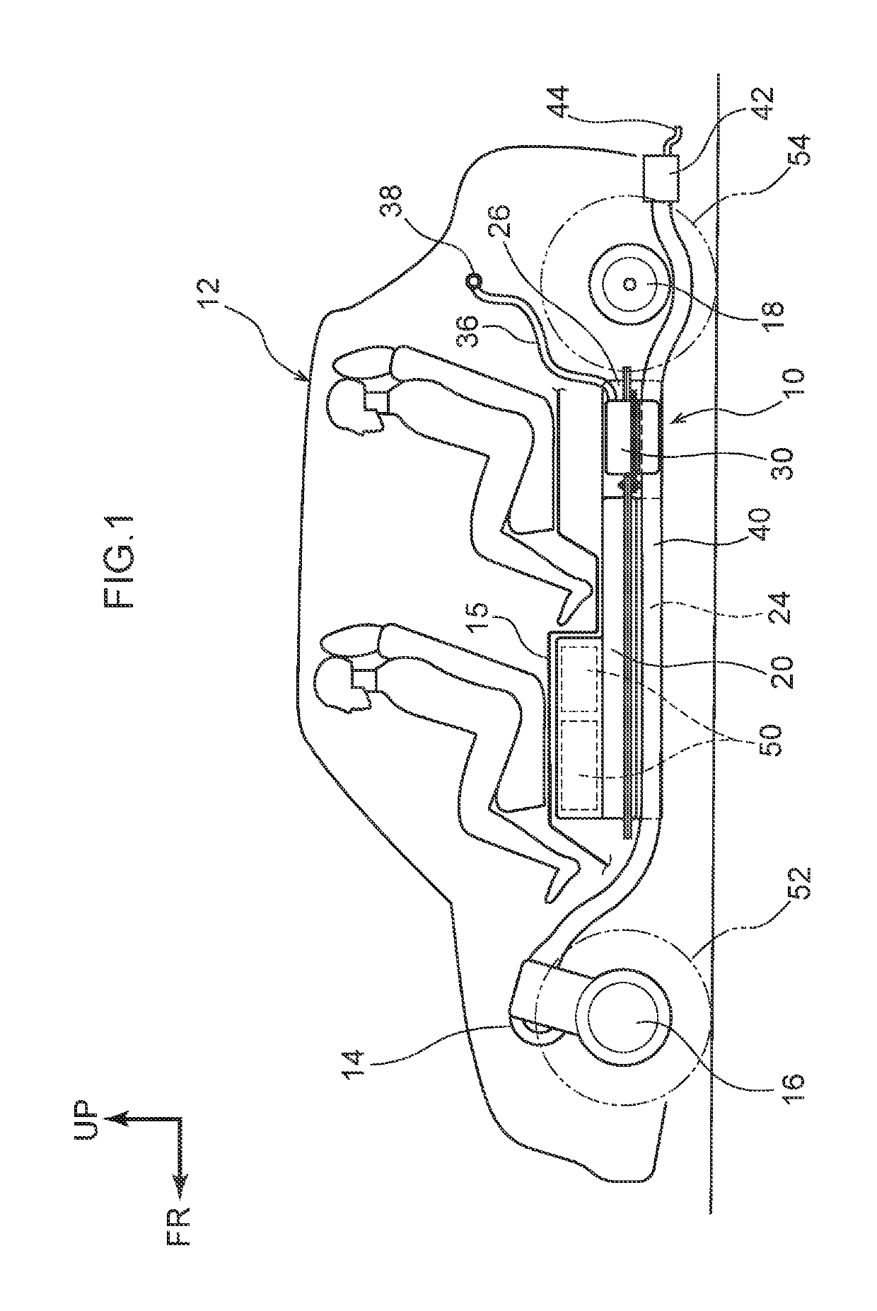
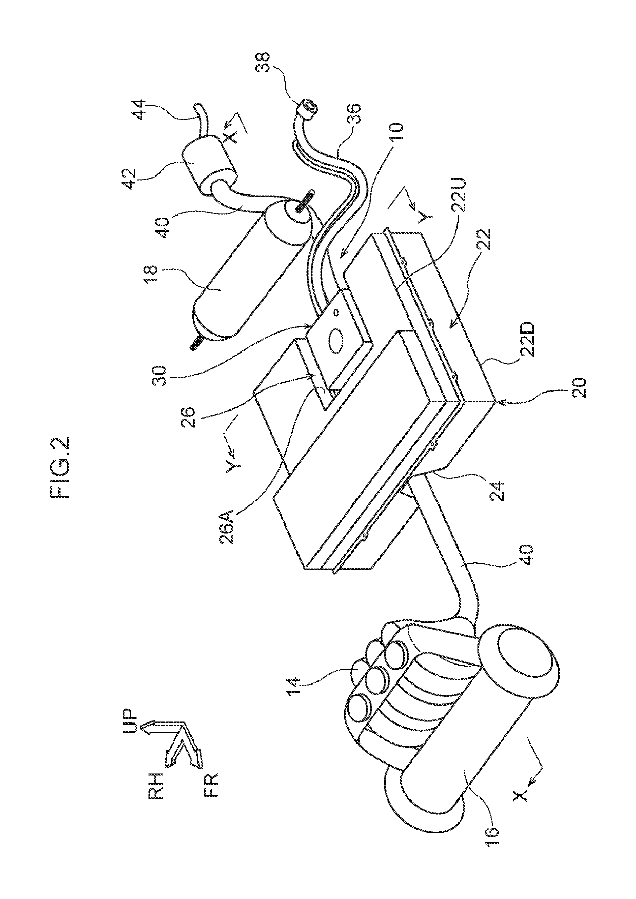
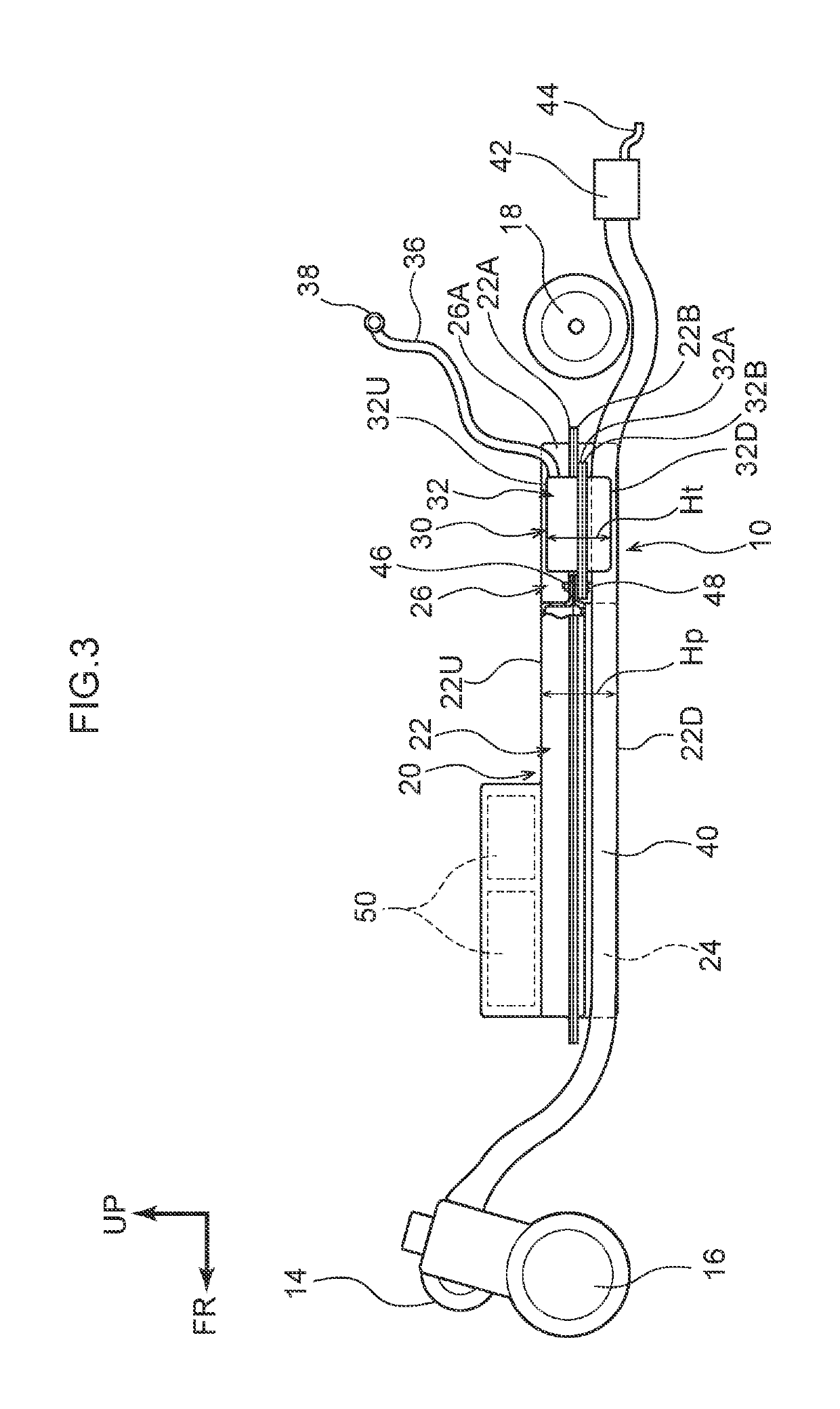
[0033]A vehicle underfloor structure 10 relating to a first embodiment is described first. As shown in FIG. 1 through FIG. 3, an engine 14 for generating electricity is installed in the front portion of a vehicle 12. A motor 16 for generating electricity is installed at the vehicle body lower side of the engine 14, and, specifically, between left and right front wheels 52. A motor 18 for traveling which is used to drive the rear wheels is installed in the rear portion of the vehicle 12, and, specifically, between left and right rear wheels 54.

[0034]The electricity generated by the engine 14 for generating electricity and the motor 16 for generating electricity is stored in a battery pack 20 that is described later. The battery pack 20 is the power source that drives the motor 18 for travelling. Namely, the vehicle 12 is a range extender vehicle that can travel a long distance by electricity.

[0035]The battery pack 20 and a fuel tank 30 are disposed between the motor 16 for generating...

second embodiment

[0062]The vehicle underfloor structure 10 relating to a second embodiment is described next. Note that regions that are equivalent to those of the above-described first embodiment are denoted by the same reference numerals, and detailed description thereof (including description of operation that is common thereto) is omitted as appropriate.

[0063]As shown in FIG. 7, in the vehicle underfloor structure 10 relating to the second embodiment, the notch-shaped portion 26 is not formed at the rear portion side of the battery pack 20, and the notch-shaped portion 26, which is substantially rectangular as seen in plan view and which opens toward the vehicle body front side, is formed in the front portion of the battery pack 20 slightly further toward the left side than the vehicle transverse direction central portion (hereinafter called “front portion center”) at the front portion of the battery pack 20.

[0064]Namely, the fuel tank 30 that is shown in FIG. 1 through FIG. 6 is provided within...

third embodiment

[0067]Finally, the vehicle underfloor structure 10 relating to a third embodiment is described. Note that regions that are equivalent to those of the above-described first embodiment and second embodiment are denoted by the same reference numerals, and detailed description thereof (including description of operation that is common thereto) is omitted as appropriate.

[0068]As shown in FIG. 8, in the vehicle underfloor structure 10 relating to the third embodiment, the notch-shaped portion 26 is not formed at the rear portion side or the front portion side of the battery pack 20. An opening portion 28, which, as seen in plan view, is formed substantially in the shape of a rectangle of approximately the same size as the fuel tank 30 and opens in the vehicle body vertical direction, is formed in the vehicle body longitudinal direction central portion of the battery pack 20 slightly further toward the left side than the vehicle transverse direction central portion thereof.

[0069]Namely, th...


PUM


Abstract

A vehicle underfloor structure has: a battery pack that is disposed beneath a floor of a vehicle, and that is a power source that drives a motor for traveling that is installed in the vehicle; and a fuel tank that is disposed beneath the floor of the vehicle, and between a vehicle body front side end portion and a vehicle body rear side end portion of the battery pack as seen in a side view, and between vehicle transverse direction both end portions of the battery pack as seen in a plan view.

Description

CROSS-REFERENCE TO RELATED APPLICATION[0001]This application is based on and claims priority under 35 USC 119 from Japanese Patent Application No. 2017-143691 filed on Jul. 25, 2017, the disclosure of which is incorporated by reference herein.TECHNICAL FIELD[0002]The present disclosure relates to a vehicle underfloor structure.RELATED ART[0003]Structures in which a battery pack is disposed beneath a floor of a vehicle, and a fuel tank is disposed beneath the floor of the vehicle and at the vehicle body rear side of the battery pack, have conventionally been proposed (see, for example, Japanese Patent Application Laid-Open (JP-A) No. 2014-19260 (Patent Document 1)).[0004]However, when the fuel tank is disposed at the vehicle body rear side of the battery pack, a strong member must be disposed at the vehicle body rear side of the fuel tank in order for collision load to not be inputted to the fuel tank at the time of a rear collision of the vehicle, and there is the concern that the w...

Claims


Application Information

Patent Timeline
Patent Type & Authority Patents(United States)
IPC IPC(8): B60K6/40B60K15/063B60K6/48B60K1/04
CPCB60K6/40B60K1/04B60K6/48B60K15/063B60Y2200/92B60K2001/0438B60K2015/0633B60K2015/0634B60K2001/0422B62D25/20B60K1/00B60K6/46B60K2001/001B60K2001/0466Y02T10/62
Inventor AJISAKA, SATOSHI
Owner TOYOTA JIDOSHA KK
Why Eureka
Try Eureka