Vehicle floor structure

a floor structure and vehicle technology, applied in the field of vehicle floor structure, can solve the problems of unlikely deformation of floor panels unlikely to be bent, etc., and achieve the effects of reducing the burden applied to floor panels, and enhancing the rigidity of floor panels

Inactive Publication Date: 2012-03-06
HONDA MOTOR CO LTD
View PDF14 Cites 19 Cited by
  • Summary
  • Abstract
  • Description
  • Claims
  • Application Information

AI Technical Summary

Benefits of technology

[0010]According to the above described vehicle floor structure, a collision load acting on the lateral frame members at the time of a frontal vehicular collision or a rear vehicular collision is directly transmitted to the side sills via the obliquely extending portions of the lateral frame member and also transmitted to the side sills via the floor panel. At least a part of the beads of the floor panel have one end each extending so as to be orthogonal to the side sill, and the other end each extending so as to be orthogonal to the lateral frame member. Consequently, the beads can receive and hold a collision load in a head-on manner. This makes the beads unlikely to be bent and makes the floor panel unlikely to be deformed. As a result, the distribution of a load over the side sills via the floor panel can be effectively performed. Furthermore, a floor frame for use in a conventional vehicle floor structure which is fixed on a floor panel for bearing a collision load acting on lateral frame members at the time of a frontal vehicular collision or a rear vehicular collision and which extends in the longitudinal direction can be omitted. Therefore, it is possible to reduce the weight of a vehicle.
[0012]In this case, a collision load at the frontal vehicular collision is directly transmitted to the side sills via the outriggers, and also to the side sills via the floor panel, and furthermore to the floor tunnel frame via the extensions. Consequently, the collision load is distributed, and hence the load burden on the floor tunnel frame and the floor panel can be decreased. As a result, a degree of reinforcement for the floor tunnel frame can be decreased, making weight reduction of the floor tunnel frame possible. A load burden on the floor panel is also decreased, making weight reduction of the floor panel also possible. Furthermore, because the other end of each of the beads extends so as to be orthogonal with respect to the vehicle width direction within a width of the front side frame, the beads can receive and hold a collision load in a head-on manner at the time of a frontal vehicular collision. This makes the beads unlikely to be bent and makes the floor panel unlikely to be deformed. As a result, distribution of a collision load over the side sills via the floor panel can be effectively performed.
[0014]In this case, a collision load at a rear vehicular collision is directly transmitted to the side sills via the obliquely extending portions of the lateral frame member, and also to the side sills via the floor panel. As a result, the load burden on the floor panel can be decreased. Furthermore, because in the lateral frame member, the connection portions between the obliquely extending portions and the linear portion are reinforced by the reinforcement members, the lateral frame member is unlikely to be deformed at the time of a rear vehicular collision. As a result, a load distribution over the side sills can be effectively performed. Furthermore, because the other end of each of the beads extends so as to be orthogonal with respect to the linear portion of the lateral frame member, the beads can receive and hold a collision load in a head-on manner at the time of a rear vehicular collision. As a result, the beads are unlikely to be bent and the floor panel are unlikely to be deformed. As a result, the distribution of a load over the side sills via the floor panel can be effectively performed.
[0016]In this case, a load acting on a vehicle body, especially on an anterior chamber, at the time of a frontal vehicular collision is transmitted to the side sills via the beads of the floor panel, and the load is also more effectively transmitted to the floor tunnel frame via the extensions. As a result, the load acting on the anterior chamber portion of the vehicle body can be more effectively distributed.
[0018]According to the above-mentioned vehicle floor structure, an impact load acting from the side sill at the time of a side vehicular collision is transmitted from the side sill to the floor panel, and also transmitted in a distributed manner from the front inclined wall and rear inclined wall of the side sill reinforcement member to the lateral frame member. As a result, the burden applied to the floor panel can be decreased. Furthermore, the provided beads enhance the rigidity of the floor panel. Consequently, the weight of the floor panel can be reduced, thus contributing to improvements in fuel efficiency. Furthermore, the load transmitted to the side sill acts on the floor tunnel frame via the floor panel, and also is transmitted in a distributed manner in the direction of the lateral frame member by the concentric arc-shaped beads starting from the inner wall of the side sill. As a result, the burden applied to the floor panel can be decreased, and the weight of the floor panel can be reduced. This can contribute to improvements in fuel efficiency.
[0019]According to the present invention, the collision load at the time of a frontal vehicular collision, a rear vehicular collision, or a side vehicular collision can be effectively distributed. Therefore the load burden on the floor panel can be decreased. Furthermore, the weight of the floor panel and the like can be reduced, which can contribute to improvements in the fuel efficiency of a vehicle.

Problems solved by technology

This makes the beads unlikely to be bent and makes the floor panel unlikely to be deformed.

Method used


Image

  • Vehicle floor structure
  • Vehicle floor structure
  • Vehicle floor structure

Examples


first embodiment

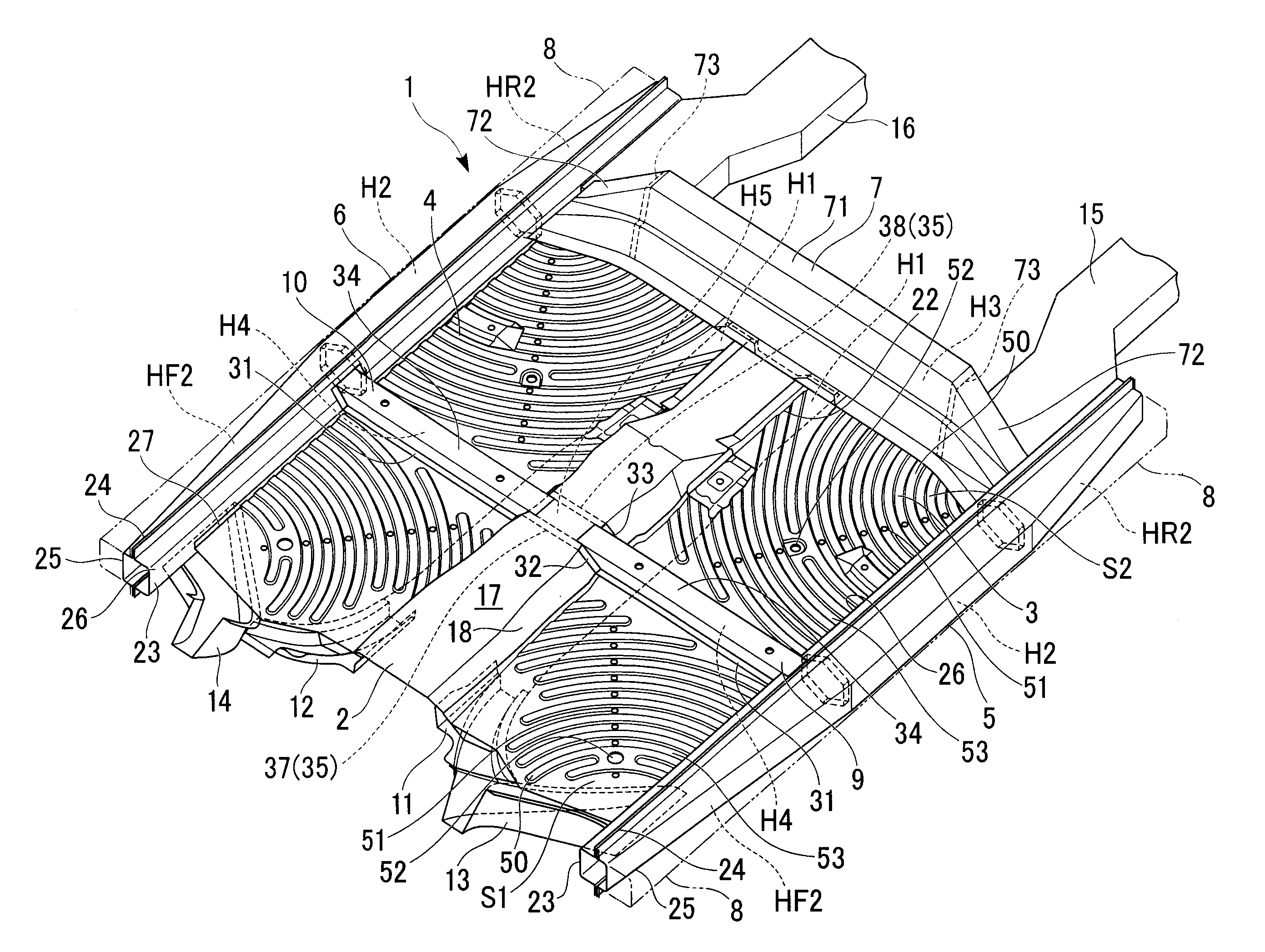
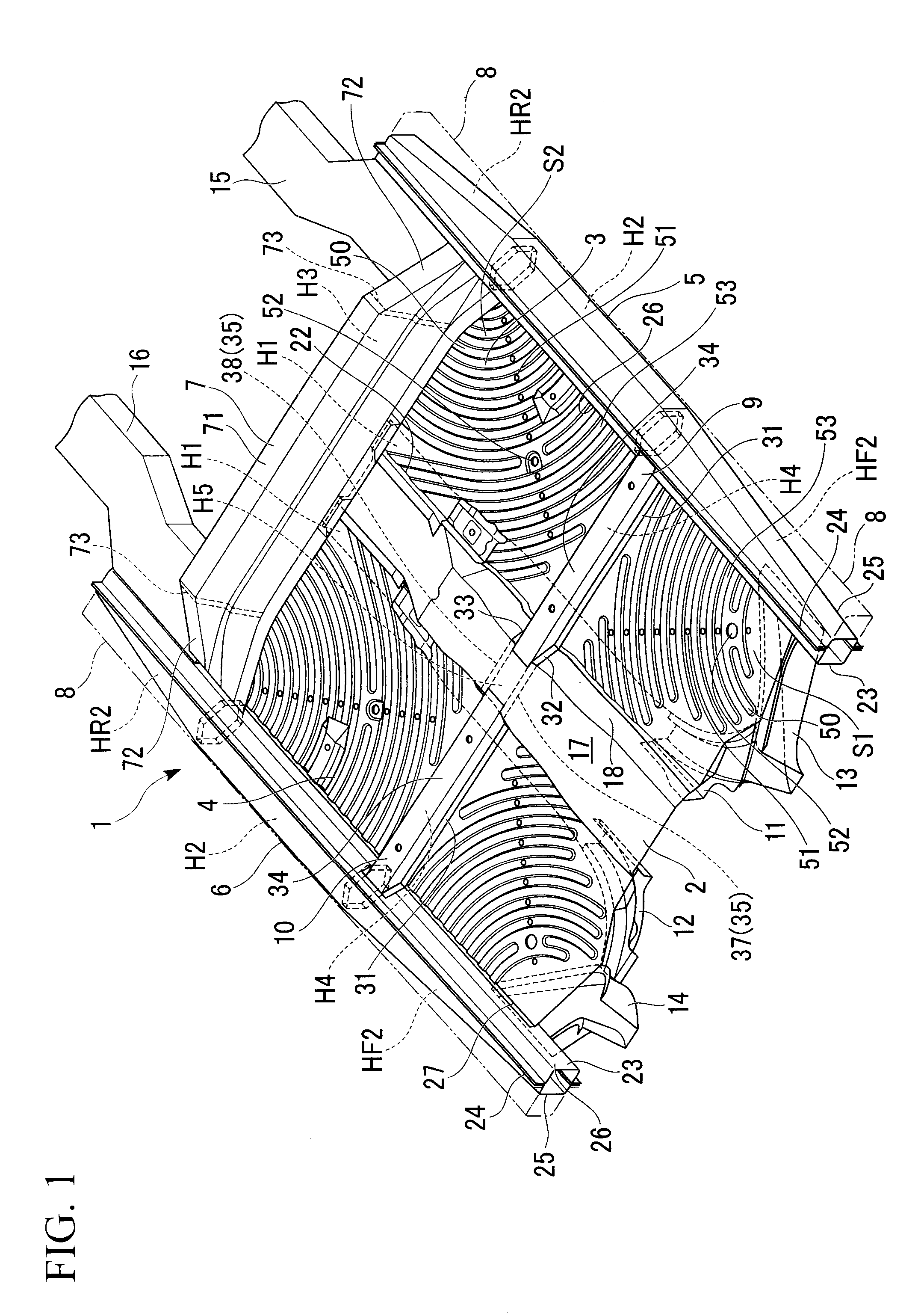
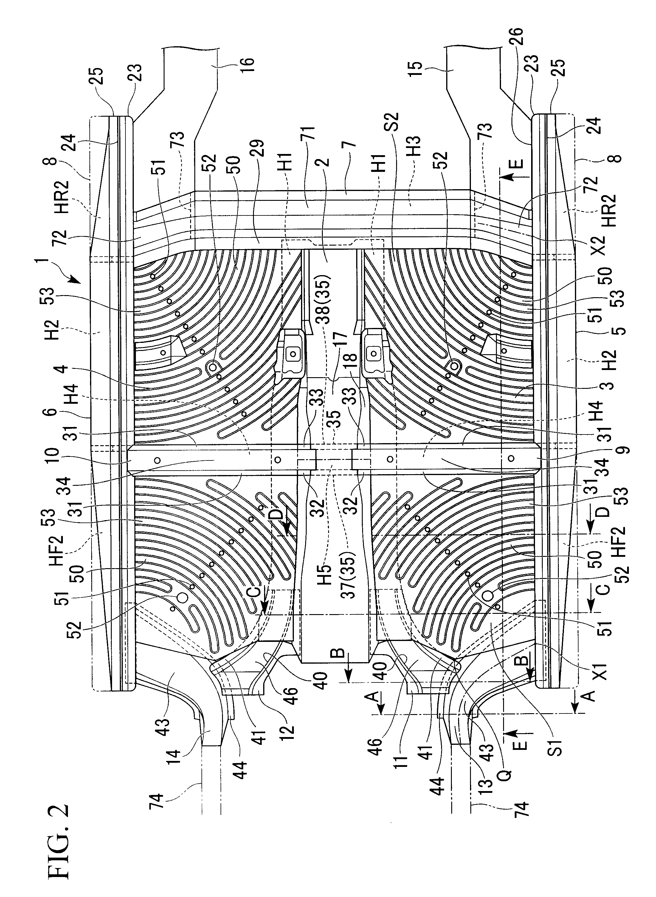
[0066]Hereunder is a description of a vehicle floor structure according to the present invention, with reference to drawings from FIG. 1 to FIG. 10. In the following description, the vertical direction, the longitudinal direction, and the lateral direction respectively refer to the vertical direction, the longitudinal direction, and the lateral direction of a vehicle body.

[0067]As shown in FIG. 1 and FIG. 2, in a floor 1 of a vehicle, a floor tunnel frame 2 extending in the vehicle length direction is formed along a central portion in the vehicle width direction. To both edges of this floor tunnel frame 2, there are joined inside edges of left and right floor panels 3, 4. To outside edges of the left and right floor panels 3, 4, there are fixed left and right side sills 5, 6, which are vehicular frame members extending in the vehicle length direction. That is, the left and right floor panels 3, 4 are bridged respectively between the floor tunnel frame 2 and the left and right side s...

second embodiment

[0100]Next is a description of the present invention based on the drawings.

[0101]As shown in FIG. 10 and FIG. 11, in a floor 101 of a vehicle, a floor tunnel frame 102 extending in the vehicle length direction is formed along a central portion in the vehicle width direction. To both edges of this floor tunnel frame 102, there are joined inside edges of left and right floor panels 103, 104. To outside edges of the left and right floor panels 103, 104, there are fixed left and right side sills 105, 106, which are vehicular frame members extending in the vehicle length direction. That is, the left and right floor panels 103, 104 are bridged respectively between the floor tunnel frame 102 and the left and right side sills 105, 106. Rear portions of the left and right side sills 105, 106 are connected to each other by means of a middle cross member 107 which is a vehicular frame member arranged in the vehicle width direction. A front edge portion of the middle cross member 107 is joined ...


PUM


Abstract

A vehicle floor structure including: a floor tunnel frame arranged along a center in a vehicle width direction and extending in a vehicle length direction; side sills arranged on the right and left sides of a vehicle body and extending in the length direction; lateral frame members connecting the tunnel frame with the side sills; floor panels bridged between the tunnel frame and the side sills; obliquely extending portions provided on at least one of the lateral frame members and extending so as to be inclined to the length direction in a planar view, connecting respectively with the side sills; and concentric arc-shaped beads provided in the respective panels, with centers respectively at intersections of the side sills and the obliquely extending portions, wherein at least one of the beads has one end extending orthogonal to the side sill and the other end extending orthogonal to the width direction.

Description

TECHNICAL FIELD[0001]The present invention relates to a vehicle floor structure. Priority is claimed on Japanese Patent Application No. 2007-111555 filed Apr. 20, 2007, and Japanese Patent Application No. 2007-111557 filed Apr. 20, 2007, the contents of which are incorporated herein by reference.BACKGROUND ART[0002]In some of the vehicle floor structures, convex-shaped or concave-shaped beads are provided over substantially the entirety of a floor panel, the beads centered around portions where side sills go across cross members (for example, see Patent Document 1).[0003]These beads can remarkably increase the rigidity of the floor panel while reducing the weight of a vehicle body. That is, in a floor panel provided with beads in this manner, a load applied to the floor panel is transmitted in directions in which the beads extend. Therefore, this property is used to transmit a collision load at the time of a frontal vehicular collision or a rear vehicular collision to side sills via...

Claims


Application Information

Patent Timeline
Patent Type & Authority Patents(United States)
IPC IPC(8): B62D25/20
CPCB62D25/2036
Inventor EGAWA, YASUHISAYASUHARA, SHIGETO
Owner HONDA MOTOR CO LTD
Why Eureka
Try Eureka