Radio communications system for controlling a vehicle

a radio communication system and vehicle technology, applied in the field of vehicle control radio communication system, can solve the problems of increasing component cost, poor expandability, and difficulty in applying wire harnesses in difficult regions to connect to wires

Inactive Publication Date: 2006-04-27
HITACHI LTD
View PDF6 Cites 24 Cited by
  • Summary
  • Abstract
  • Description
  • Claims
  • Application Information

AI Technical Summary

Benefits of technology

[0004] As a kind of a vehicle control apparatus, there is, for example, an electronic vehicle control system which senses a state quantity of a control object such as a quantity of driver's operation on driving means such as an acceleration pedal or an airflow rate of intake manifold of engine by using a sensor, transfers a sensing signal converted to an electric signal by the sensor to an electronic control unit (hereafter referred to as ECU) in a vehicle, and controls the vehicle by using an electronic control throttle and electronically controlled fuel injection valves. As compared with conventional systems in which transfer is conducted by a mechanical mechanism or a hydraulic mechanism, the following can be mentioned as advantages of the electronic vehicle control system: flexible and sophisticated unified running control using a computer can be implemented; the weight of the vehicle can be decreased; and it becomes possible to extend design freedom.
[0005] On the other hand, in the conventional vehicle control system, signals of sensors for monitoring the manipulated variables of control pedals and so on given by the driver and the vehicle state are input to the ECU via wires, and control signals directed to a throttle serving as a vehicle control actuator and so on are output from the ECU by wires. A wire portion between the ECU and the sensor & actuator portion is called wire harness. The environment in which the ECU is placed is an environment exposed to dust and raindrops, such as an engine compartment of the vehicle. Therefore, very high reliability is required of a connection portion between the wire harness and the ECU. Pursuing the reliability leads to an increase in component costs.
[0007] As described in JP-A-2003-002019, a technique for replacing the wire harness between the ECU and the sensor & actuator portion with radio communication in order to solve the problems is known. In JP-A-2003-002019, however, attention is not paid to the fact that there are a plurality of routes as regards a relay route for a radio communication signal. Even if one of relay points fails, it is effective in improving the failure resistance to transmit data via another relay point. However, the conventional radio communication system as described in JP-A-2003-229798 is the so-called nonreal time communication system in which limitation of the time for transmitting the information is not severe, although it is considered to transmit information certainly.
[0009] An object of the present invention is to provide a vehicle control radio communication system capable of solving the problems and reconciling the reliability concerning the communication and the real time property.
[0011] According to the present invention, the load in the radio transmission line can be distributed by associating reliability required of data with reliability of a radio communication route and selecting a radio communication route. The real time property (real time response property) and reliability concerning the radio transmission in the vehicle control radio communication system can be ensured.

Problems solved by technology

Pursuing the reliability leads to an increase in component costs.
Furthermore, if the combination of the sensors and actuators connected to the ECU is altered, not only control software on the ECU but also the wire harness must be altered because of the wire connection, resulting in a problem of poor expandability.
Furthermore, it is difficult to apply the wire harness to regions where wire connection is difficult, such as an air pressure sensor in a tire which is a rotating body.
Furthermore, a problem of fuel cost aggravation is also caused by an increase in weight of the wire harness itself.

Method used


Image

  • Radio communications system for controlling a vehicle
  • Radio communications system for controlling a vehicle
  • Radio communications system for controlling a vehicle

Examples


Embodiment Construction

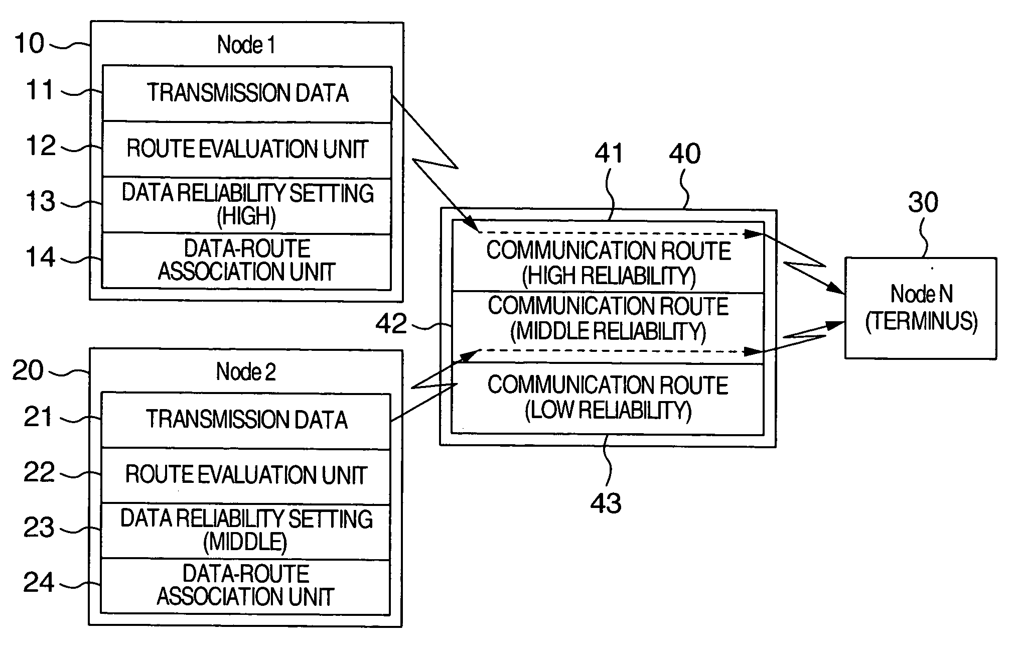
[0032] Hereafter, a vehicle control radio communication system according to an embodiment of the present invention will be described with reference to the drawings. FIG. 1 is a diagram showing an outline of a system configuration example of a vehicle control radio communication system according to an embodiment of the present invention. As shown in FIG. 1, the radio communication system according to the present embodiment includes a first transmission node (node 1) 10, a second transmission node (node 2) 20, a reception node (node N) 30, and a communication route 40. The number of transmission nodes and reception node is nothing but an example. Typically, at least one sensor is provided in each node.

[0033] As shown in FIG. 1, the first transmission node 10 includes transmission data 11, a route evaluation unit 12 for evaluating the reliability and communication time of a communication relay route, a data reliability setting unit 13 for setting reliability required of the transmissi...


PUM


Abstract

A radio control system for controlling a vehicle includes a transmission node for transmitting vehicle control data, the vehicle control data including at least one of a measured value of a vehicle state or a driver's manipulated variable and a control target value of a control actuator in the vehicle, a reception node for receiving the vehicle control data, and a plurality of radio communication routes between the transmission node and the reception node. A radio communication route that satisfies communication limit time of transmission data including the vehicle control data and satisfies lowest required reliability of the transmission data is selected from among the radio communication routes.

Description

BACKGROUND OF THE INVENTION [0001] The present invention relates to a system for transmitting and receiving data by communication in a vehicle control system. In particular, the present invention relates to a vehicle control radio communication system for controlling the vehicle by using radio communication. [0002] As a conventional radio communication system, there is a method of detecting a transmission quality of a transmission line from a plurality of relay routes, storing the information about the transmission qualities of the relay routes in a quality descending order, selecting a relay route having the best transmission quality at the time of data transmission, and transmitting data (see, for example, JP-A-2003-229798 (P.9 and FIG. 7)). [0003] As for a communication system intended for vehicles, a technique for conducting communication between a sensor and a control unit by radio in order to measure an air pressure in a tire which is a rotating body is disclosed (see, for exa...

Claims


Application Information

Patent Timeline
Patent Type & Authority Applications(United States)
IPC IPC(8): G06F17/00H04L45/121
CPCH04L12/40H04L12/42H04L45/121H04L2012/40273H04W84/18
Inventor YOSHIMURA, KENTAROMORITA, YUICHIROSHIMURA, TAKANORIMIYAZAKI, MASAYUKI
Owner HITACHI LTD
Why Eureka
Try Eureka