Armor shielding

a shielding and armor technology, applied in the field of blast and ballistic shielding, can solve the problems of low weight efficiency compared to other available systems, steel and aluminum metallic armor exposed to buildings and transportation infrastructure, and particularly vulnerable targets of terrorist activity, and achieve the effect of high strength

Inactive Publication Date: 2011-04-19
COMPOSITE TECH CO LLC
View PDF84 Cites 20 Cited by
  • Summary
  • Abstract
  • Description
  • Claims
  • Application Information

AI Technical Summary

Benefits of technology

[0021]As a result of the present invention, a shielding system is provided that is relatively inexpensive and has acceptable weight efficiency. The benefit of the armor shielding of the present invention concerns the potential for defeating modern aggressive threats while reducing vehicle weight. Various steel alloys used in armaments are approximately 500-600 lbs per cubic foot and are very expensive. In contrast, an ultra high performance concrete ballistic liner according to the present invention weighs approximately 167 per cubic foot. Such high performance concrete is not readily attachable to vehicles that are made primarily of steel. Therefore, this invention incorporates such a high performance concrete into composite assemblies utilizing various metals which are more easily attached to a vehicle chassis by welding, screwing, hinging, etc. and are lighter in weight than solid metal armor.

Problems solved by technology

Exposed structural elements of buildings and transportation infrastructure are particularly vulnerable targets for terrorist activity.
However, the steel and aluminum metallic armor has several drawbacks, including low weight efficiency compared to other available systems, such as composite systems.
Titanium systems, on the other hand, typically perform better than steel and aluminum, but titanium is extremely expensive and may be cost prohibitive for many applications.

Method used


Image

  • Armor shielding
  • Armor shielding
  • Armor shielding

Examples


Embodiment Construction

[0041]The present invention provides a shield that is relatively inexpensive and is easily constructed, which shields vehicles, personnel and existing structures from a projectile, such as a bullet, and / or an explosive blast and fire. The shield can be adapted to be incorporated, assembled or otherwise secured on a moving vehicle, or the shield can be installed on an existing stationary structure, or the shield can be worn by a person. As used herein, the term “structure” is meant to encompass both stationary structures, such as commercial and residential buildings, bridges, tunnels, radio or television broadcast towers, viaducts, pipelines and the like, as well as moving vehicles, including automobiles, buses, trains, ships, airplanes, military vehicles etc. Moreover, while the term “structure” is used frequently herein to refer to the thing being shielded, the shield of the present invention is adaptable to shield human personnel and other living things.

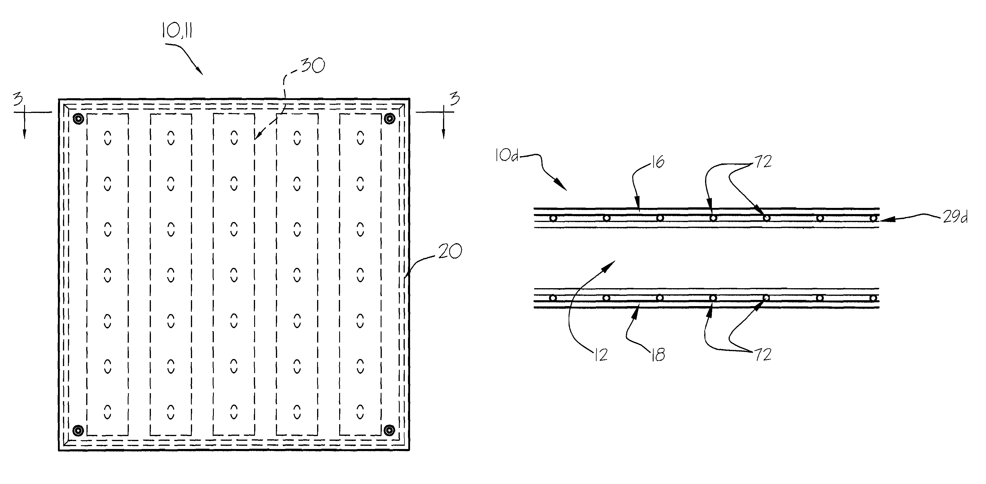
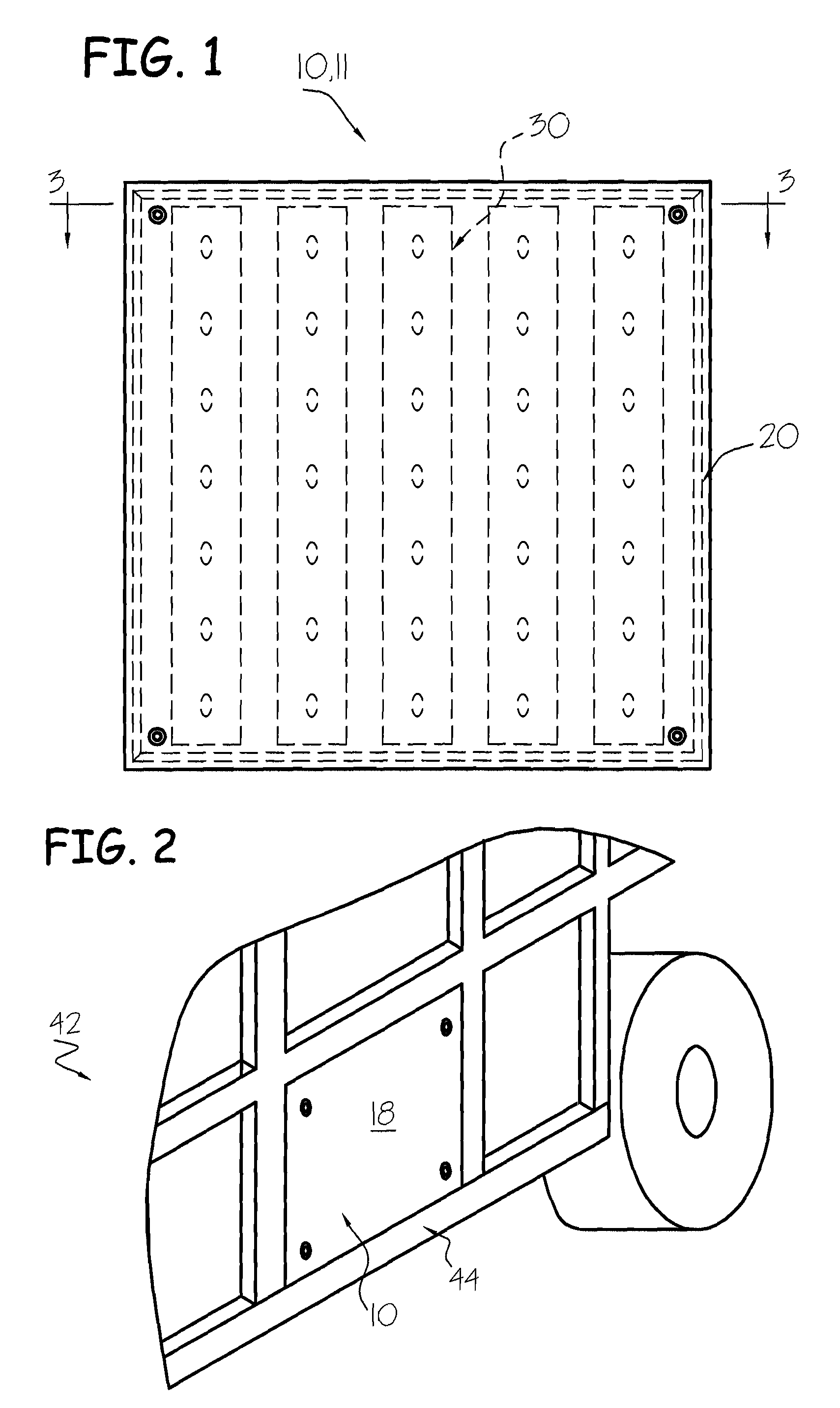
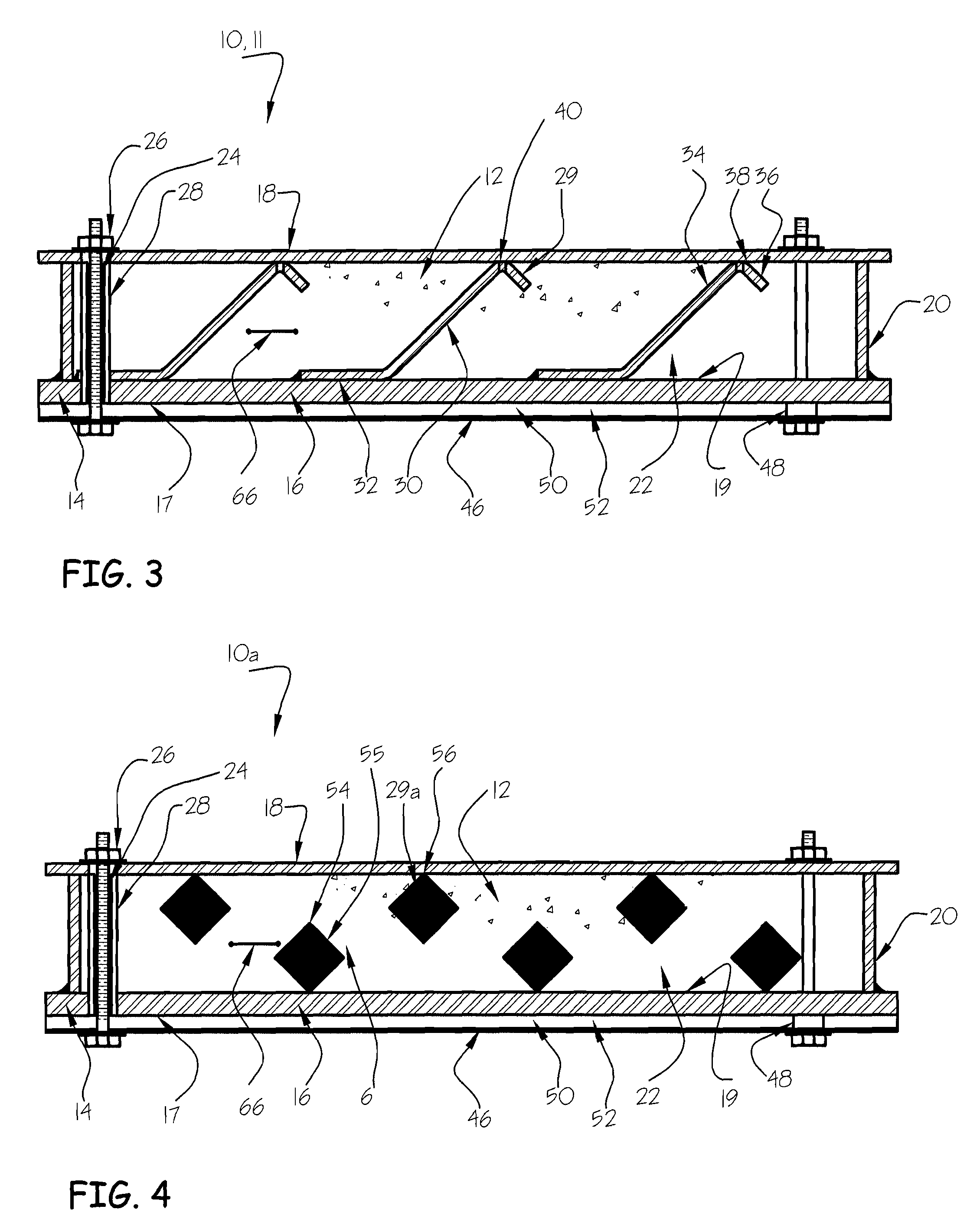
[0042]FIGS. 1-3 illustrate ...


PUM

PropertyMeasurementUnit
flexural strengthaaaaaaaaaa
thicknessaaaaaaaaaa

Abstract

A shield for shielding structures, vehicles and personnel from a projectile and / or an explosive blast generally includes a substantially planar shield plate adapted for attachment to a structure to provide protection to the structure. The shield plate includes a chassis having an interior surface facing the structure and an opposite outer surface, and a ballistic liner disposed on the outer surface of the chassis such that the chassis is more proximal the structure than the ballistic liner. The ballistic liner has an exterior surface facing the exterior environment.

Description

BACKGROUND OF THE INVENTION[0001]The present invention relates generally to blast and ballistic shielding and more particularly to energy absorbing armor shielding for existing structures and vehicles, as well as personnel, which provides protection especially from projectiles with and without the effects of a blast.[0002]Due to increased threats and awareness of potential terrorist activities, increased attention is being given to protecting structures of all types against damage from projectiles, fire, explosion, and other threats, malicious and accidental. Exposed structural elements of buildings and transportation infrastructure are particularly vulnerable targets for terrorist activity. Thus, there is a need for projectile-resistant and blast and / or ballistic impact shielding for use in both existing and new construction for vehicles and exposed structures.[0003]Ballistic threats do not remain the same over time. Military organizations, terrorists and insurgents are always look...

Claims


Application Information

Patent Timeline
Patent Type & Authority Patents(United States)
IPC IPC(8): F41H5/04
CPCF41H1/02F41H5/013F41H5/0421F41H5/0492F42D5/05F41H5/0442Y10T29/49826Y02B10/20
Inventor HALLISSY, GERALDHIGBIE, WILLIAM G.
Owner COMPOSITE TECH CO LLC
Why Eureka
Try Eureka