Eureka AIR delivers breakthrough ideas for toughest innovation challenges, trusted by R&D personnel around the world.

Image forming apparatus

Active Publication Date: 2014-11-13
RICOH KK
View PDF1 Cites 11 Cited by
  • Summary
  • Abstract
  • Description
  • Claims
  • Application Information

AI Technical Summary

Benefits of technology

This patent text describes an image forming apparatus with a toner container that can be easily inserted. The apparatus has a unique design with an upper wall and a projecting bottom wall that creates a recess where toner can flow through. This allows for smoother and more efficient toner delivery during printing. The design also includes a shutter to control when the toner outlet is open or closed. This invention makes it easier to maintain and use the image forming apparatus, which can improve efficiency and reliability.

Problems solved by technology

As toner therein is consumed, such toner containers become empty and replaced.
The increase in the toner containing capacity, however, results in the increase in size of the toner container, and the image forming apparatus incorporating the toner container becomes bulkier.

Method used


Image

  • Image forming apparatus
  • Image forming apparatus
  • Image forming apparatus

Examples


Embodiment Construction

[0037]In describing preferred embodiments illustrated in the drawings, specific terminology is employed for the sake of clarity. However, the disclosure of this patent specification is not intended to be limited to the specific terminology so selected, and it is to be understood that each specific element includes all technical equivalents that operate in a similar manner and achieve a similar result.

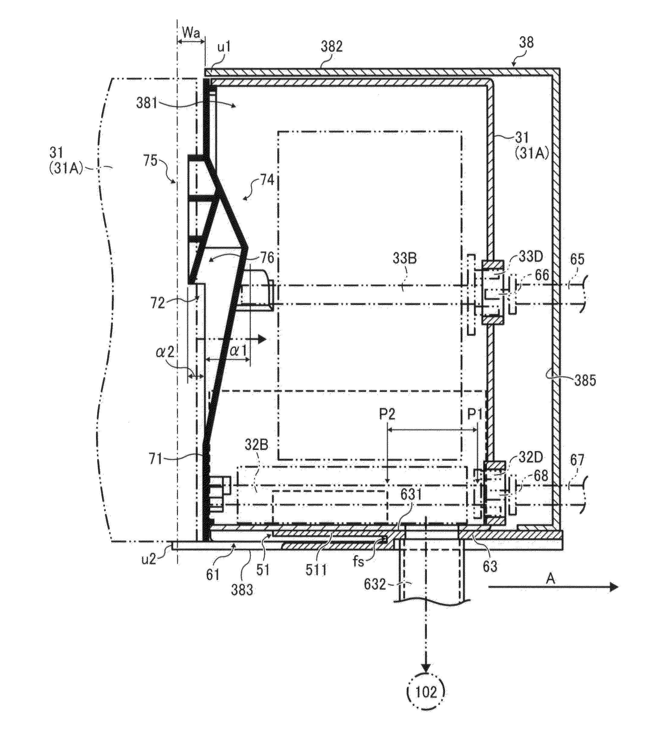
[0038]The inventor of the present invention recognizes that, in the case of a toner container employing a toner containing body including a plug that is disengaged from a mouthpiece member of the toner containing body simultaneously with installation of the toner container, the possibility of a malfunction is high when the position is deviated.

[0039]Further, according to understanding of the inventor of the present invention, in the case of a toner container including a handle and produced by blow molding, toner tends to accumulate on the back side of the handle, thus increasing the amo...


PUM


Abstract

An image forming apparatus includes an insertion entrance through which a toner container is inserted, and an entrance peripheral wall surrounding the insertion entrance and including an upper wall and a projecting bottom wall projecting beyond the upper wall to an upstream side in an insertion direction in which the toner container is inserted. The toner container includes a toner outlet in a substantially center portion of a bottom of the toner container in a width direction perpendicular to the insertion direction and a shutter to open and close the toner outlet. A recess recessed in the insertion direction is provided in a center portion of the projecting bottom wall in the width direction, and the recess in the projecting bottom wall is longer than the shutter in the width direction.

Description

CROSS-REFERENCE TO RELATED APPLICATION[0001]This patent application is based on and claims priority pursuant to 35 U.S.C. §119 to Japanese Patent Application No. 2013-098909, filed on May 8, 2013, in the Japan Patent Office, the entire disclosure of which is hereby incorporated by reference herein.BACKGROUND OF THE INVENTION[0002]1. Technical Field[0003]Embodiments of the present invention generally relate to an image forming apparatus, such as a copier, a printer, a facsimile machine, a plotter, or a multifunction machine (so-called multifunction peripheral or MFP) having at least two of coping, printing, facsimile transmission, plotting, and scanning capabilities and further relate to an image forming apparatus including a mount in a body thereof to which a toner container is removably installed.[0004]2. Description of the Background Art[0005]Generally, electrophotographic image forming apparatuses such as copiers, printers, facsimile machines, or multifunction machines (MFPs) inc...

Claims


Application Information

Patent Timeline
IPC IPC(8): G03G15/08
CPCG03G15/0875G03G21/1676
Inventor KATSUYAMA, GORO
Owner RICOH KK
Why Eureka
Eureka Blog
Learn More