Rear view camera system using rear view mirror location

a rear view camera and mirror technology, applied in closed circuit television systems, color television details, television systems, etc., can solve the problems of increased blocking of the rearward view from the center-placed rear view mirror, blind spots may still occur, and view through the rear view mirror may also be obscured, so as to improve the frame of reference

Active Publication Date: 2014-11-20
FORD GLOBAL TECH LLC
View PDF7 Cites 61 Cited by
  • Summary
  • Abstract
  • Description
  • Claims
  • Application Information

AI Technical Summary

Benefits of technology

[0006]The present invention configures a rearview camera system to present an image to the driver using a display mounting location and / or visual cues to improve their frame of reference for interpreting the displayed image.

Problems solved by technology

Due to the many tradeoffs between mirror field of view, mounting locations, and interference by other solid vehicle structures, blind spots may still occur.
For example, a trend toward increased head rest size has resulted in increased blocking of the rearward view from the center-located rear view mirror.
The view through the rear view mirror may also be obscured by temporary objects in the interior such as rear seat passengers and cargo or by glare from headlamps of other vehicles.
Regardless of window size, the buildup of dirt, frost, or snow which may sometimes occur on the back window may obscure the view obtained with the rear view mirror.
The reverse-view display screen is activated while in reverse gear to help the driver check for any objects in their backup path, but it is typically deactivated during forward driving since the video can be distracting or may be confusing to the driver because of possible difficulties in integrating the reverse camera view into their mental frame of reference of the surroundings.

Method used


Image

  • Rear view camera system using rear view mirror location
  • Rear view camera system using rear view mirror location
  • Rear view camera system using rear view mirror location

Examples


Embodiment Construction

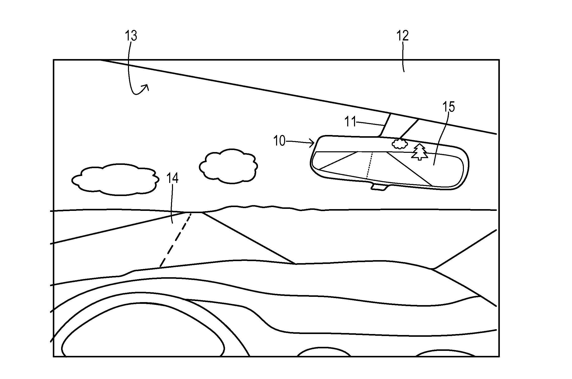
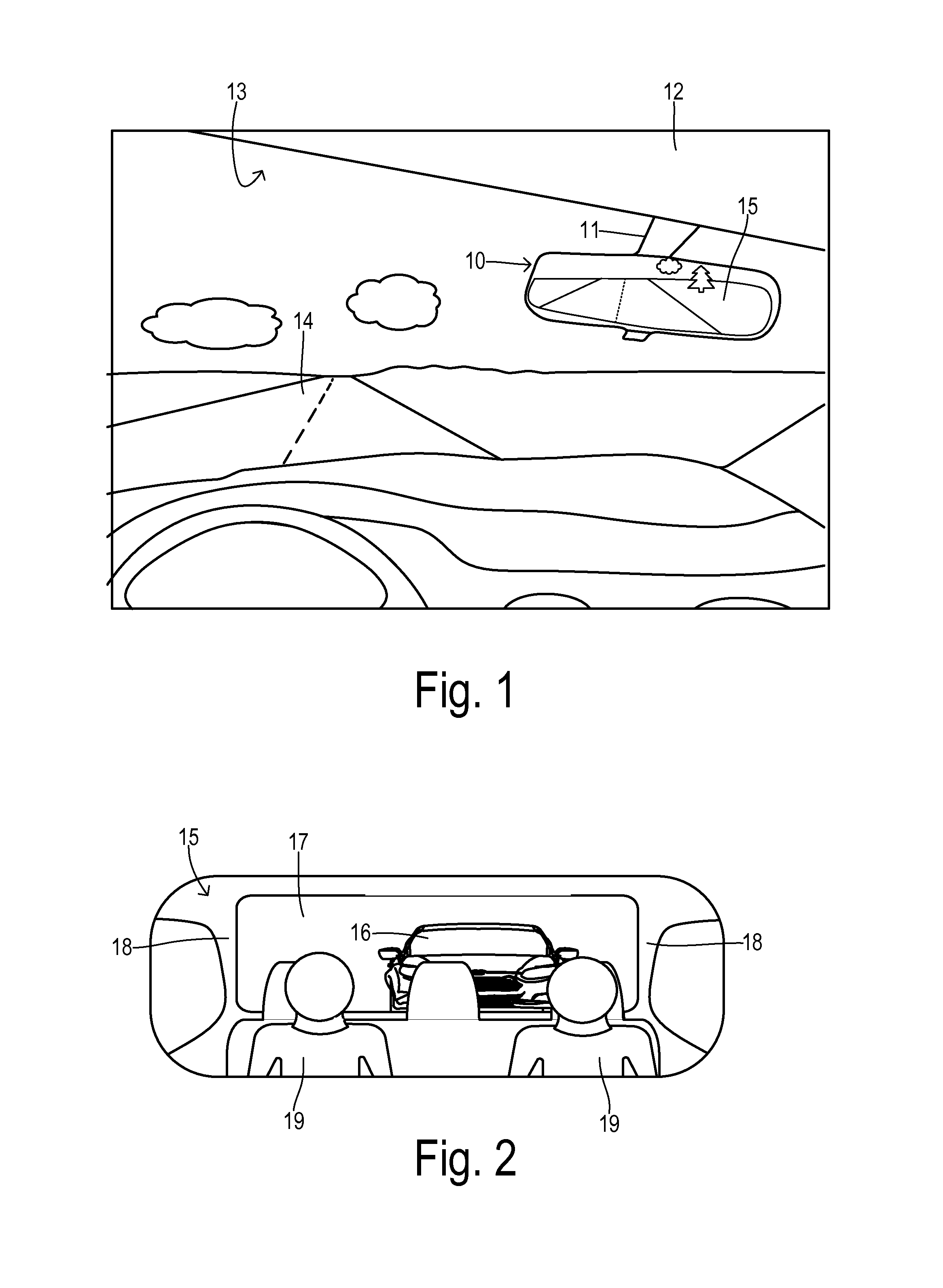
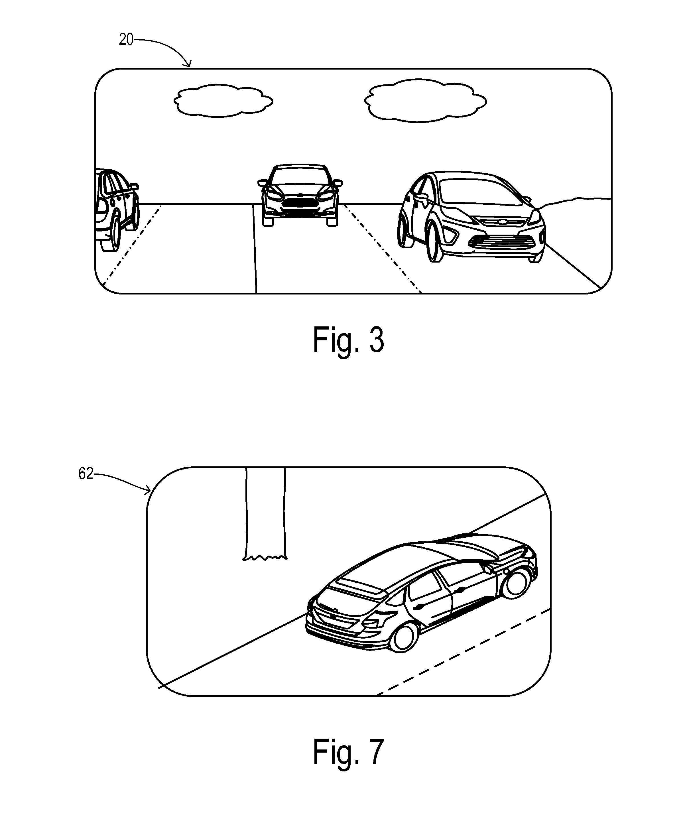
[0017]In a primary embodiment of the present invention, the conventional (relatively narrow-angle) rearview mirror is replaced by an LCD screen showing a 180° or greater rear view from rearward and / or side facing camera(s). A sufficiently wide view can be obtained which could allow door-mounted side view mirrors to be eliminated. For example, a flat panel screen is pivotably mounted with a similar size, shape, and position as a traditional rear view mirror and provides a live camera image behind and / or to the side of the vehicle. This provides a view without obstructions from rear passengers, headrests, or roof pillars. In cold climates, the camera lens will be much quicker to clean / de-ice than the entire rear window. Furthermore, the invention reduces styling restrictions related to rear vision / obscuration that would otherwise exist for a mirror system.

[0018]In addition to the unobstructed view from the exterior-mounted rear cameras, the invention provides the driver with a vehicle...


PUM


Abstract

A rearward viewing system for an automotive vehicle comprises an image display mounted proximate to a front windshield of the vehicle. An exterior image sensor captures a first image directed externally of the vehicle with a first field of view. An internal image sensor captures a second image directed internally of the vehicle with a second field of view. An image integrator merges the first and second images according to a predetermined alignment of the first and second fields of view, wherein the second image is muted in the merged image so that the first image is emphasized when displayed on the image display.

Description

CROSS REFERENCE TO RELATED APPLICATIONS[0001]Not Applicable.STATEMENT REGARDING FEDERALLY SPONSORED RESEARCH[0002]Not Applicable.BACKGROUND OF THE INVENTION[0003]The present invention relates in general to driver vision systems, and, more specifically, to a rear view camera system using an external camera with a large field of view together with an internal camera and display providing contextual information to the driver.[0004]Conventional vision aids enabling a driver to monitor the surroundings behind and to the side of a vehicle include externally-mounted side view mirrors and an internally-mounted rear view mirror. Mirror placement and shapes have been manipulated in attempts to minimize blind spots. Due to the many tradeoffs between mirror field of view, mounting locations, and interference by other solid vehicle structures, blind spots may still occur. For example, a trend toward increased head rest size has resulted in increased blocking of the rearward view from the center-...

Claims


Application Information

Patent Timeline
Patent Type & Authority Applications(United States)
IPC IPC(8): B60R11/04
CPCB60R11/04B60R1/00B60R2300/303
Inventor VOJTISEK, MARK G.MILLER, MICHAEL J.GALE, CARLA A.KREDER, RICHARD A.SPIETH, MARY C.
Owner FORD GLOBAL TECH LLC
Why Eureka
Try Eureka