Railway point crank system

a crank system and point crank technology, applied in the direction of railway tracks, mechanical devices, belts/chains/gearings, etc., can solve the problem that the torque applied is not necessarily enough to rotate the crank, and achieve the effect of cost effectiv

Active Publication Date: 2014-11-27
SPX FLOW TECH ENGLAND LTD
View PDF11 Cites 4 Cited by
  • Summary
  • Abstract
  • Description
  • Claims
  • Application Information

AI Technical Summary

Benefits of technology

[0006]Some embodiments in accordance with the present invention therefore look to resolve these issues to provide a further alternative system that can more cost effectively be implemented.
[0007]Some embodiments in accordance with the present invention provide a railway point crank system that provides power directly to the linked cranks, thus reducing the load on the point machine. This is done through a component which is able to be plugged-in and hooked up to existing systems, and can run off of electrical, pneumatic or hydraulic power.
[0008]This power can be to apply a torque to the linked cranks. That applied torque is not necessarily enough to rotate the crank. Instead it may be simply to reduce the torque (and hence power) that the point machine is required to output to actuate the linked cranks. This reduces wear and breakdown of point machines.

Problems solved by technology

That applied torque is not necessarily enough to rotate the crank.

Method used


Image

  • Railway point crank system
  • Railway point crank system
  • Railway point crank system

Examples


Embodiment Construction

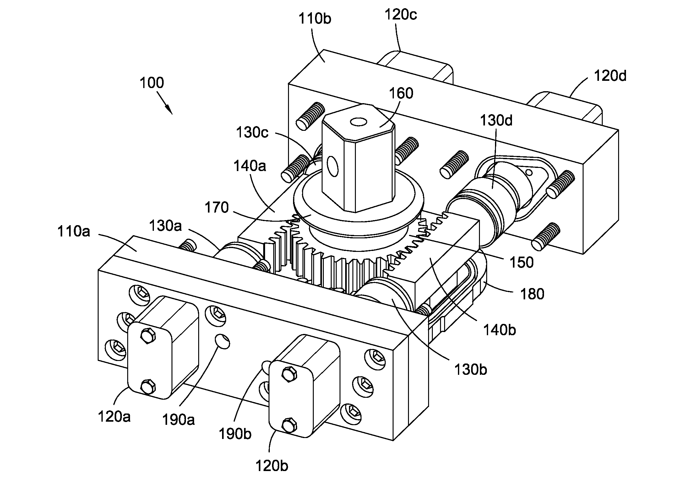
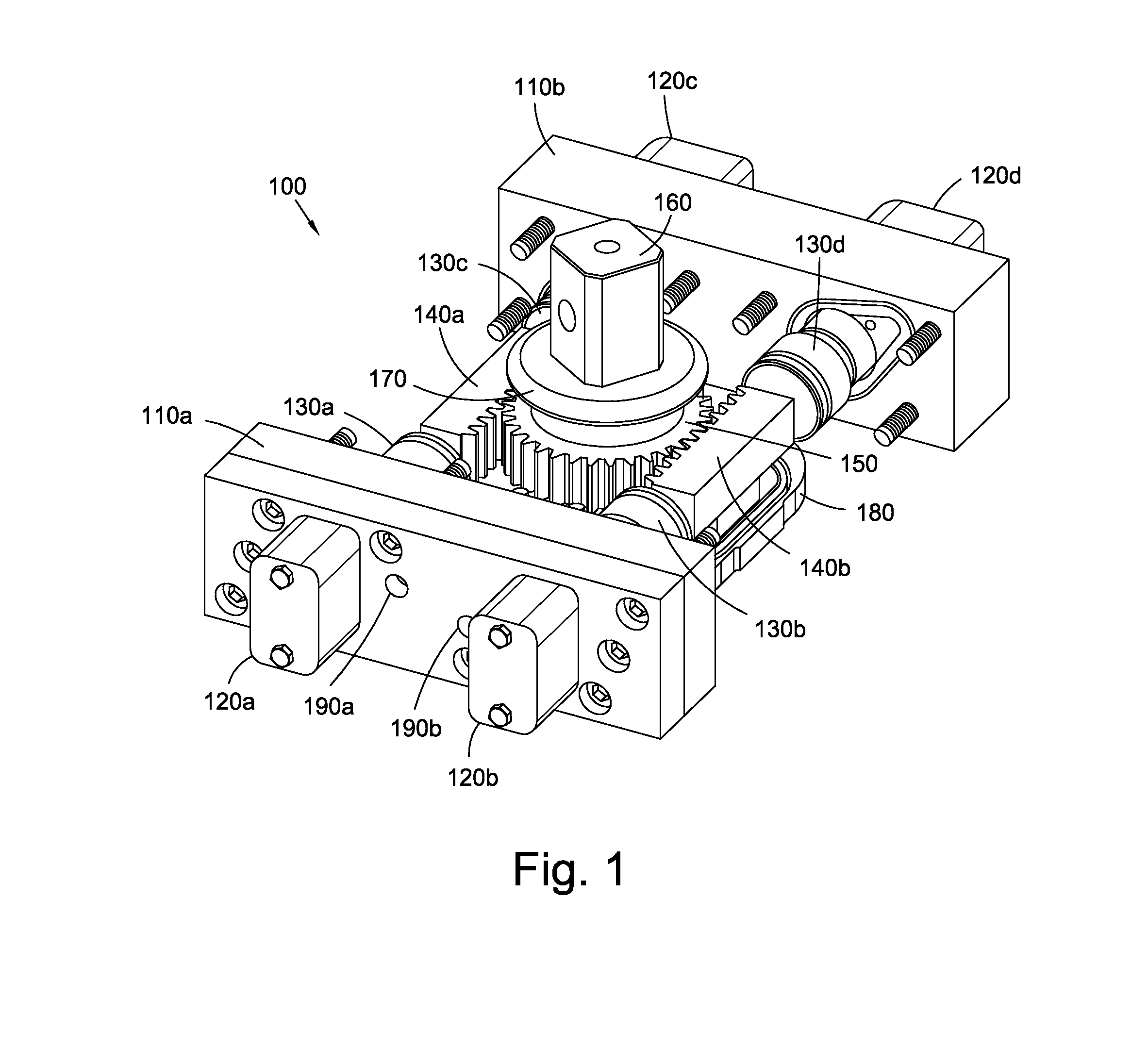
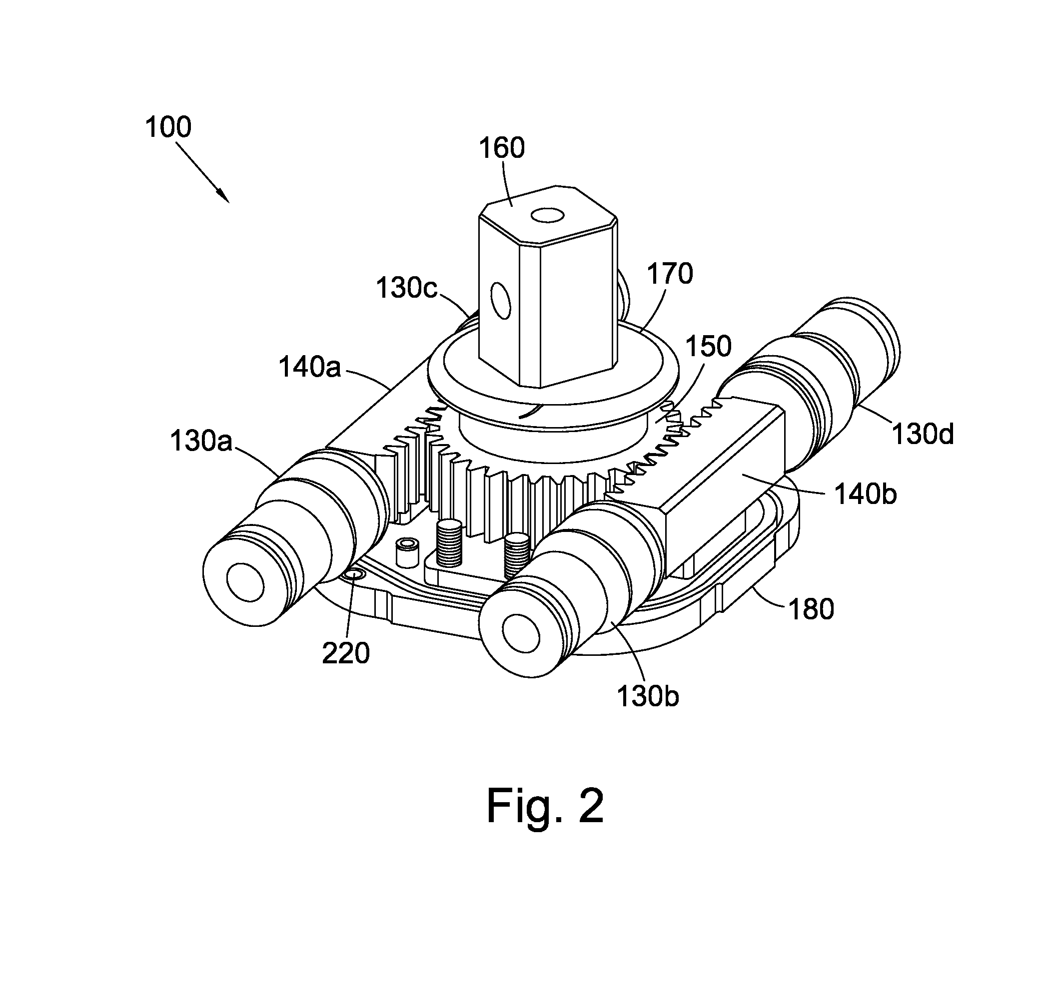
[0101]FIGS. 1 and 2 illustrate a number of components of a linked crank mounting device 100. In FIG. 1, two manifolds 110 are located in a parallel and spaced apart arrangement. In this embodiment the two manifolds are rectangular. They form the two ends of the device 100.

[0102]Each manifold houses a number of attachment bolts for securing the manifolds 110 and neighbouring components in place.

[0103]The manifolds 110 of this embodiment are made out of metal and regulate hydraulic fluid flow into pistons 130.

[0104]Extending from the end surface of each manifold 110 are two removable dust covers 120. These dust covers 120 are bolted onto the manifold 110, house the end portions of hydraulic pistons 130 during operation, and in this embodiment are located approximately a quarter of the manifold's length in from either end of the respective manifold 110. The dust covers prevent the ingress of dirt and moisture.

[0105]In this embodiment, under the dust covers is a bleed nipple to allow bl...


PUM


Abstract

The present disclosure relates to a linked crank mounting device for use with a switch rail, comprising: an input terminal or series of input terminals; an actuator; an output connector; and attachment means for rigidly attaching the linked crank mounting device relative to the railway; wherein the input terminal or terminals are for receiving input power, the output connector is directly or indirectly mechanically linked to at least one of a switch rail or an output connector of a further linked crank mounting device, and the actuator applies the input power to the output connector.

Description

FIELD OF THE INVENTION[0001]The present invention relates to a railway point crank system, and in particular a powered railway point crank system for moving and holding switch rails.BACKGROUND[0002]Switch rails are present at all railway turn-outs, and allow trains to change tracks. This is achieved by having an extra pair of rails present—the switch rails—which can be moved from a position where they do not interfere with the standard rails and the train wheels, into a position where the train wheels are diverted on to one or more of the switch rails, and so the train is diverted onto the turn-off. The radius of the turn off required (and hence length of the switch rails) varies depending on a number of factors including the terrain and the speed of the train at that section of track.[0003]The switch rails are required to move within strict dimensional limits. Often, the tip of the switch rail is driven into position by a point machine located between, or at the side of the tracks,...

Claims


Application Information

Patent Timeline
Patent Type & Authority Applications(United States)
IPC IPC(8): E01B7/00
CPCE01B7/00B61L5/02B61L5/04B61L5/06B61L5/065Y10T74/18184
Inventor CHADDA, IQBAL SINGHPINK, TODD CHRISTOPHERCOOPER, JAMES ERVIN
Owner SPX FLOW TECH ENGLAND LTD
Why Eureka
Try Eureka