Systems and methods for controlling warnings at vehicle crossings

a vehicle crossing and warning technology, applied in the field of vehicle location systems and methods, can solve the problems of long warning time, inability to accurately predict the speed of vehicles, and inability to accurately control the warning at the crossing,

Active Publication Date: 2014-12-18
GENERAL ELECTRIC CO
View PDF10 Cites 17 Cited by
  • Summary
  • Abstract
  • Description
  • Claims
  • Application Information

AI Technical Summary

Benefits of technology

[0014]In an embodiment, a system includes a timing determination module configured to be disposed onboard an approaching vehicle system. The timing determination module is configured, during travel of the approaching vehicle system along a first route toward a crossing between the first route and a second route, to determine one or more arrival times of the approaching vehicle system to reach the crossing and to repeatedly communicate notification messages having the one or more arrival times to a remote crossing system that is configured to activate one or more warning devices disposed at or near the crossing to notify other vehicles on the second route that the approaching vehicle system is approaching the crossing along the first route. The timing determination module is configured to determine the one or more arrival times at different respective locations along the first route as the approaching vehicle system travels toward the crossing.
[0015]In an embodiment, a method includes determining, onboard an approaching vehicle system, one or more arrival times of the approaching vehicle system during travel of the approaching vehicle system along a first route toward a crossing between the first route and a second route. The method also includes repeatedly communicating notification messages with the one or more arrival times to a remote crossing system that is configured to activate one or more warning devices disposed at or near the crossing to notify other vehicles on the second route that the approaching vehicle system is approaching the crossing along the first route. The one or more arrival times are determined at different respective locations along the first route as the approaching vehicle system travels toward the crossing.

Problems solved by technology

In some systems, for example rail systems that use catenaries or third rails to provide energy to rail vehicles, electrical interference may be too high for predictor systems to function accurately.
Long warning times can be undesirable because of the unnecessary delay caused to operators of other vehicles trying to move through the crossing.
Traditional predictor circuits are limited by practical considerations to a range extending a given distance from a crossing.
In such systems, crossings will frequently activate earlier than desired, resulting in overly long waiting periods, and resulting in inconsistent wait times for operators of vehicles waiting at the crossing.
Such systems also fail to address issues resulting from relatively slower speeds of the vehicle that is approaching the crossing.
Because only a single message is communicated from the onboard system to the wayside unit, this single message may not be received and / or may be degraded or interfered with due to various problems with communication and / or external interferences with communication.
Because of this additional, built-in buffer time period, the warning system may activate too soon and other vehicles at the crossing may be warned of the approaching vehicle too soon.
As described above, impatient operators of these other vehicles may attempt to circumvent such a warning system by attempting to drive through the crossing ahead of the approaching vehicle.

Method used


Image

  • Systems and methods for controlling warnings at vehicle crossings
  • Systems and methods for controlling warnings at vehicle crossings
  • Systems and methods for controlling warnings at vehicle crossings

Examples


Embodiment Construction

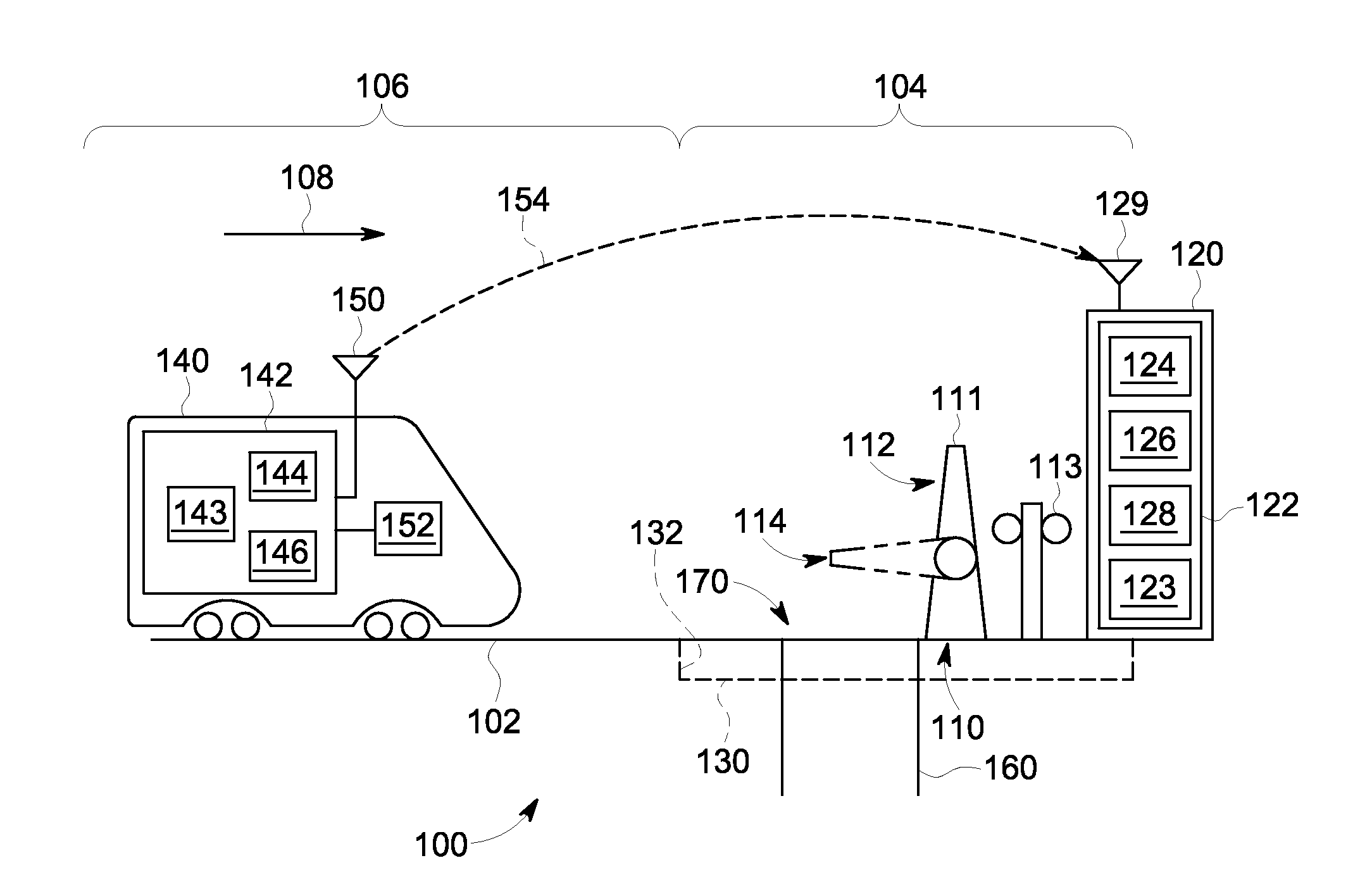
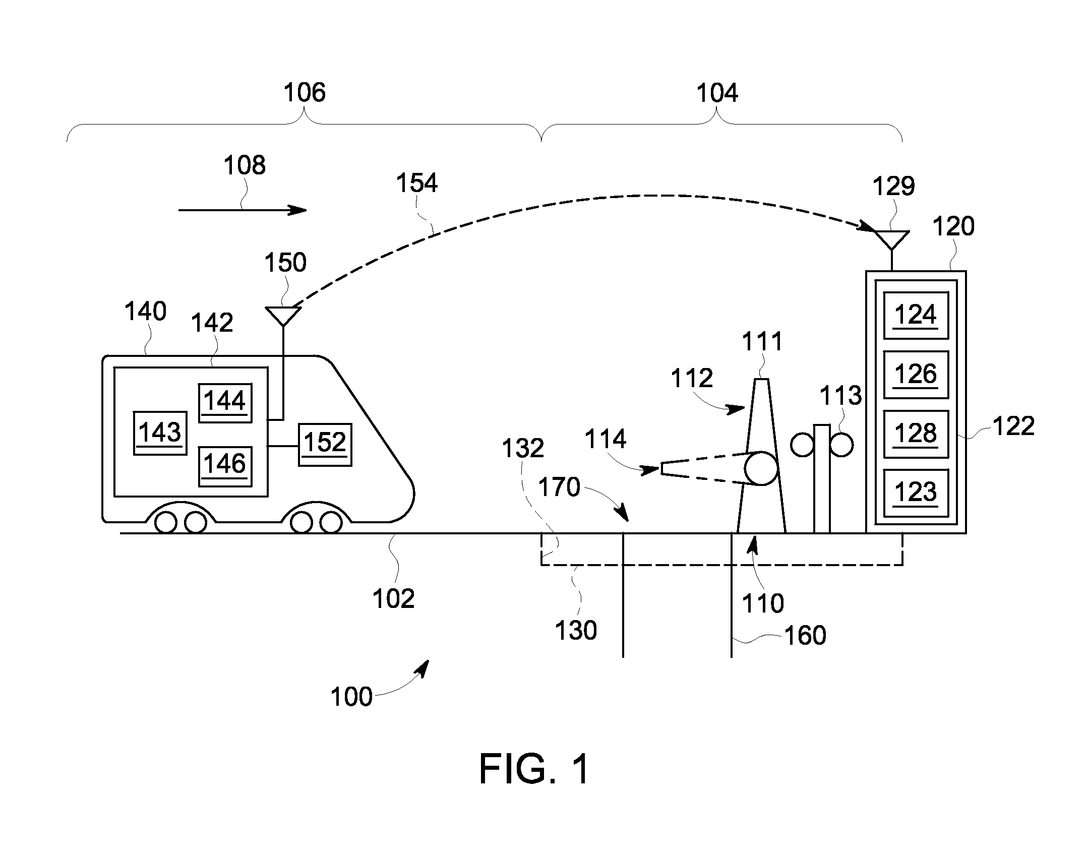
[0026]One or more embodiments of the inventive subject matter described herein provide systems and methods for improved operation of crossings for transportation systems, such as crossings associated with an intersection between a rail system and a road or highway system. In various embodiments, an onboard system is provided that is configured to control movement of a rail vehicle and to communicate with a remote crossing system or system, such as wayside equipment controlling the crossing. The control systems for the rail vehicle, for example, may be configured to be compatible with Positive Train Control (PTC) systems utilized in the United States. In various embodiments, bidirectional communications between onboard equipment and wayside equipment may be used to activate and deactivate crossing warning (or closing) systems when necessary to provide a substantially consistent amount of warning time. For example, the crossing warning systems may be activated no longer than a designa...


PUM


Abstract

A system includes a timing determination module configured to be disposed onboard an approaching vehicle system during travel of the approaching vehicle system along a first route toward a crossing between the first route and a second route. The timing determination module is configured to determine one or more arrival times of the approaching vehicle system to reach the crossing and to repeatedly communicate notification messages having the one or more arrival times to a remote crossing system that is configured to activate one or more warning devices disposed at or near the crossing to notify other vehicles on the second route that the approaching vehicle system is approaching the crossing along the first route. The timing determination module is configured to determine the one or more arrival times at different respective locations along the first route as the approaching vehicle system travels toward the crossing.

Description

CROSS-REFERENCE TO RELATED APPLICATIONS[0001]This application is related to U.S. patent application Ser. No. 13 / 910,412, which was filed on 5 Jun. 2013, and is titled “Systems And Methods For Providing Constant Warning Time At Crossings,” the entire disclosure of which is incorporated by reference.[0002]This application claims priority to U.S. Provisional Patent Application No. 61 / 835,854, which was filed on 17 Jun. 2013, and is titled “Systems And Methods For Controlling Warnings At Vehicle Crossings,” the entire disclosure of which also is incorporated by reference.FIELD[0003]Embodiments of the subject matter described herein relate to vehicle location systems and methods, and more particularly, to systems and methods for providing warning times at crossings.BACKGROUND[0004]A vehicle transportation system may include routes over which vehicles travel. These routes may cross routes of other transportation systems, such as where rail tracks and road or highway systems cross over eac...

Claims


Application Information

Patent Timeline
Patent Type & Authority Applications(United States)
IPC IPC(8): B61L29/00
CPCB61L29/00B61L23/00B61L25/021B61L25/025B61L29/22B61L29/32
Inventor STEFFEN, II, MICHAELFRIES, JEFFREY MICHAELWEINGARTNER, ARIC ALBERTSHIELDS, WILLIAMBOYD, SHERRI
Owner GENERAL ELECTRIC CO
Why Eureka
Try Eureka