
Thermal printer

a printer and thermal technology, applied in the field of thermal printers, can solve the problems of insufficient lock inability to lock itself, and component precision errors, and achieve the effects of suppressing the looseness of the platen roller (the platen unit), suppressing the occurrence of paper jam and the like, and high quality printing

Active Publication Date: 2015-01-01
SEIKO INSTR INC
View PDF2 Cites 5 Cited by
  • Summary
  • Abstract
  • Description
  • Claims
  • Application Information

AI Technical Summary

Benefits of technology

The printer described in this patent prevents the platen roller from getting loose on the printer cover, which can cause variations in printing quality and even paper jams. This is achieved by using a biasing member that pushes the platen unit towards the printer cover, securing it in place and preventing any variations in its position with respect to the printer head. Additionally, the printer cover is reinforced from the inside to ensure even pressure on the whole platen unit, regardless of how the printer cover is positioned. This eliminates the need for one-side lock and ensures high-quality printing.

Problems solved by technology

However, practically, there is some component precision error, assembly error, or the like.
Thus, when the printer cover is closed, failure such as insufficient lock of the platen roller, impossible lock itself, and non-uniform contact of the whole platen roller with the thermal head is occasionally caused even when lock is possible.
However, the above-described conventional technique still has a following issue.
As a result, failure of so-called one-side lock where only the one bearing member side is locked and the other bearing member side is not locked or sufficiently locked is occasionally caused.
When one-side lock is caused, the platen roller does not come into contact with the thermal head with uniform and appropriate contact pressure, causing defective printing and degradation of printing quality, and also causing occasional paper jam or the like.

Method used


Image

  • Thermal printer
  • Thermal printer
  • Thermal printer

Examples


Embodiment Construction

[0035]A description will hereinafter be given of an embodiment of the present invention with reference to the accompanying drawings.

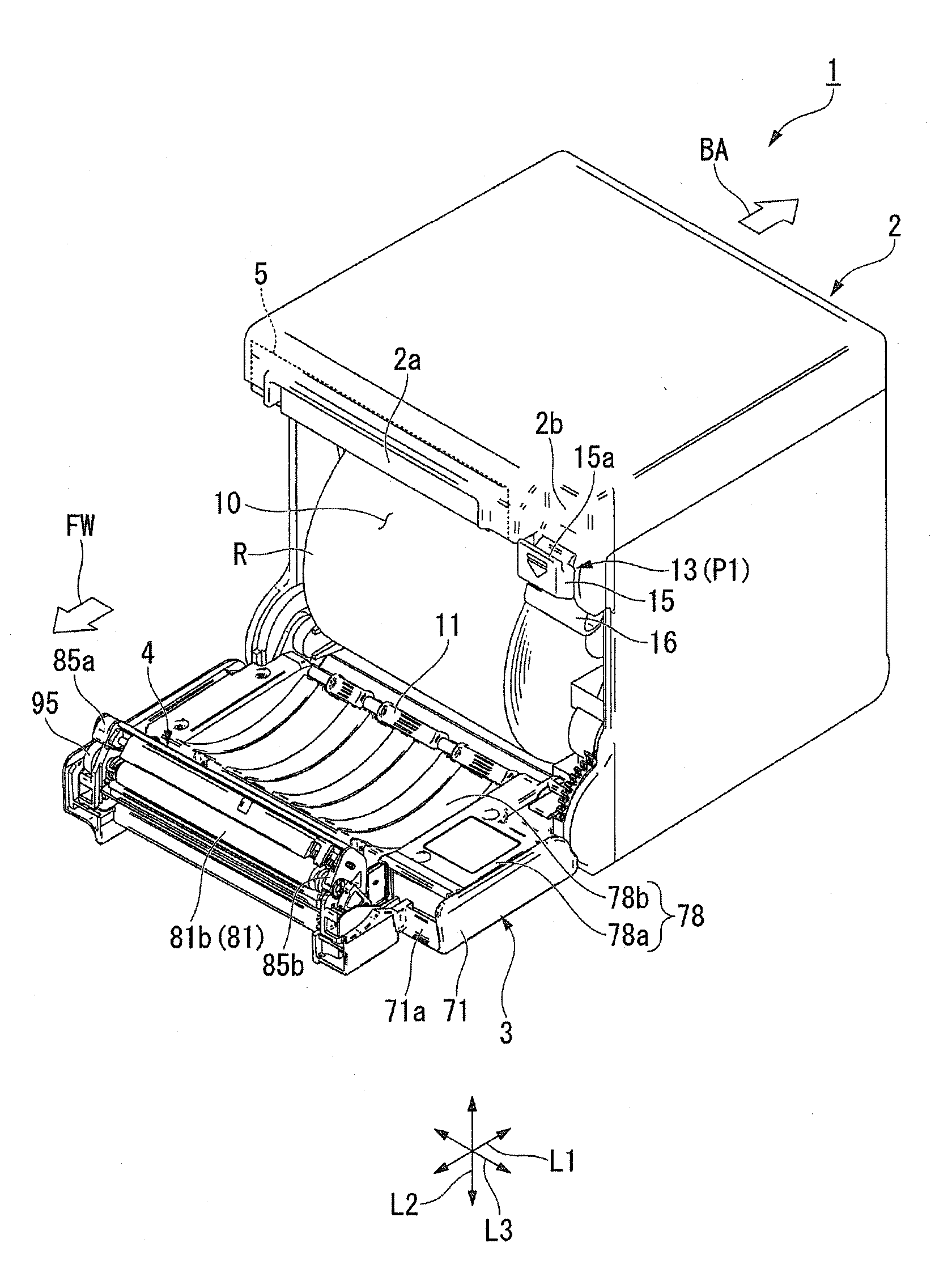
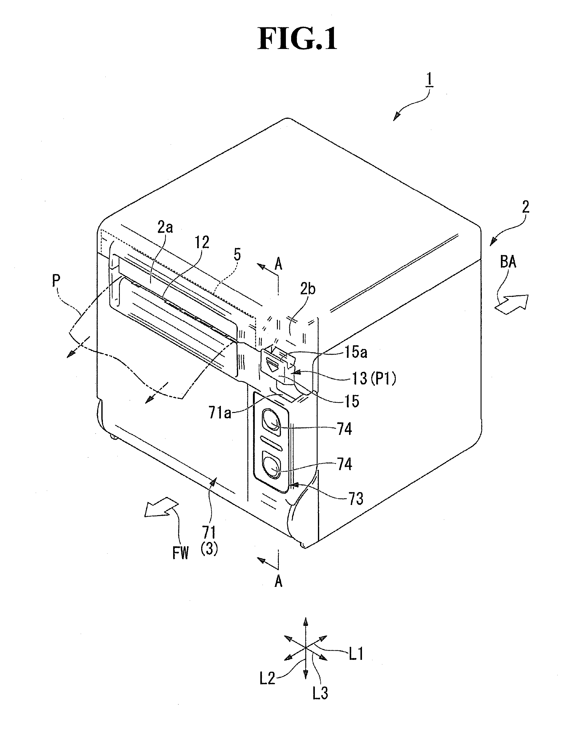
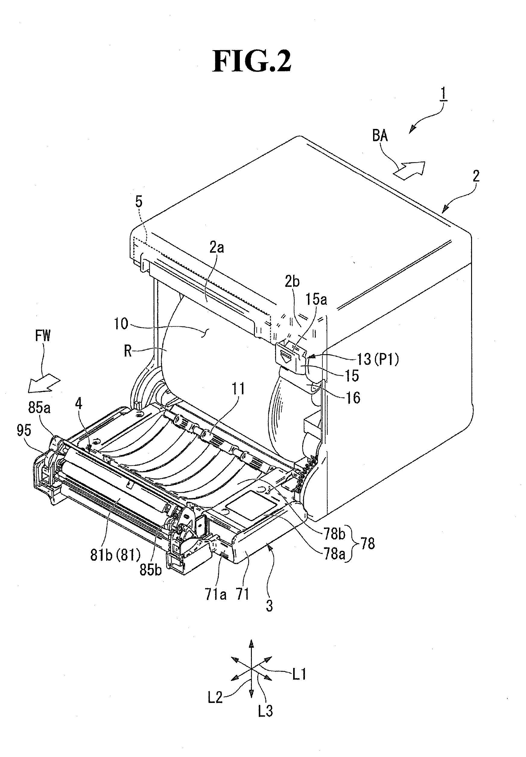
[0036]FIG. 1 is a perspective view illustrating a thermal printer 1 with the printer cover 3 at a closed position. FIG. 2 is a perspective view illustrating the thermal printer 1 with the printer cover 3 at an open position, and FIG. 3 is a front view of the thermal printer 1 with the printer cover 3 at the closed position. As illustrated in FIGS. 1 to 3, the thermal printer 1 of this embodiment is a printer that prints on recording paper P (thermal paper) drawn from the roll paper R (refer to FIG. 2), allowing the recording paper P to be used as a ticket, a receipt, or the like. The thermal printer 1 includes a casing 2, the printer cover 3, a platen unit 4 (refer to FIG. 2) provided on the printer cover 3 side, and a head unit 5 (refer to FIG. 2) provided on the casing 2 side.

[0037]In this embodiment, when the printer cover 3 is at the closed position...


PUM


Abstract

A thermal printer comprises: a casing that houses recording paper; a printer cover connected to the casing in a manner turnable around a first shaft; a head unit provided on the casing and including a thermal head; and a platen unit provided on the printer cover, assembled to the head unit in a manner releasable along with open / close operation of the printer cover, and including a platen roller, wherein the platen unit is mounted on the printer cover in a manner turnable around a second shaft that is parallel to the first shaft and slidable along a direction perpendicular to the second turning shaft, and the thermal printer further includes a biasing member that biases the platen unit in a direction away from the printer cover out of turn directions of the platen unit around the second shaft is provided between the printer cover and the platen unit.

Description

BACKGROUND OF THE INVENTION[0001]1. Field of the Invention[0002]The present invention relates to a thermal printer.[0003]2. Description of the Related Art[0004]As a thermal printer, there is known a structure including a line thermal head (hereinafter, simply referred to as a thermal head) and a platen roller to be in contact with the thermal head that are assembled in a manner releasable (separation type). In such a separation type thermal printer, for example, a head unit including a thermal head is mounted on a side of a case that houses roll paper, and a platen unit including the platen roller is mounted on a side of a printer cover connected to the case in such a manner that the platen roller can be opened / closed. According to this structure, the thermal head and the platen roller can be assembled in a manner releasable along with open / close operation of the printer cover. Therefore, workability upon setting of recording paper, upon paper jam handling, upon maintenance, replace...

Claims


Application Information

Patent Timeline
Patent Type & Authority Applications(United States)
IPC IPC(8): B41J29/02
CPCB41J29/02B41J29/13B41J29/38
Inventor AIZAWA, KAZUYUKI
Owner SEIKO INSTR INC
Learn More