Vapor storage device having a diffuser plate and dome

a technology of diffuser plate and vapor storage device, which is applied in the direction of machines/engines, transportation items, separation processes, etc., can solve the problems of fuel vapor leakage or permeation of the fuel tank, vapor generation, and inability to provide the desired flow distribution in the device, so as to reduce the emissions and reduce the vapor emissions

Active Publication Date: 2015-01-22
FORD GLOBAL TECH LLC
View PDF13 Cites 2 Cited by
  • Summary
  • Abstract
  • Description
  • Claims
  • Application Information

AI Technical Summary

Benefits of technology

[0002]Vapor storage canister, such as carbon canisters, are used in vehicles to reduce vapor emissions caused by temperature changes in the vehicle. For instance, temperature shifts in the fuel tank which may be caused by diurnal cycles, heat rejection from underbody components such as exhaust pipe and/or hot return fuel from engine can generate fuel vapors in the fuel delivery system. Fuel vapor is also generated during refueling because of air entrainment with liquid fuel, turbulence and temperature difference between tank fuel and fresh fuel. Furthermore for hybrid vehicles, fuel tank is sealed at high pressure. This pressure is released rapi

Problems solved by technology

This pressure change can also cause vapor generation.
The fuel vapors may leak or permeate from the fuel tank if not properly sequestered.
However, the fuel vapor storing device disclosed in U.S. Pat. No. 8,246,729 does not provide a desired amount of flow distribution in the device during purging.
Specifically, the tubular diffuser may not generate flow patterns which evenly distribute

Method used


Image

  • Vapor storage device having a diffuser plate and dome
  • Vapor storage device having a diffuser plate and dome
  • Vapor storage device having a diffuser plate and dome

Examples


Embodiment Construction

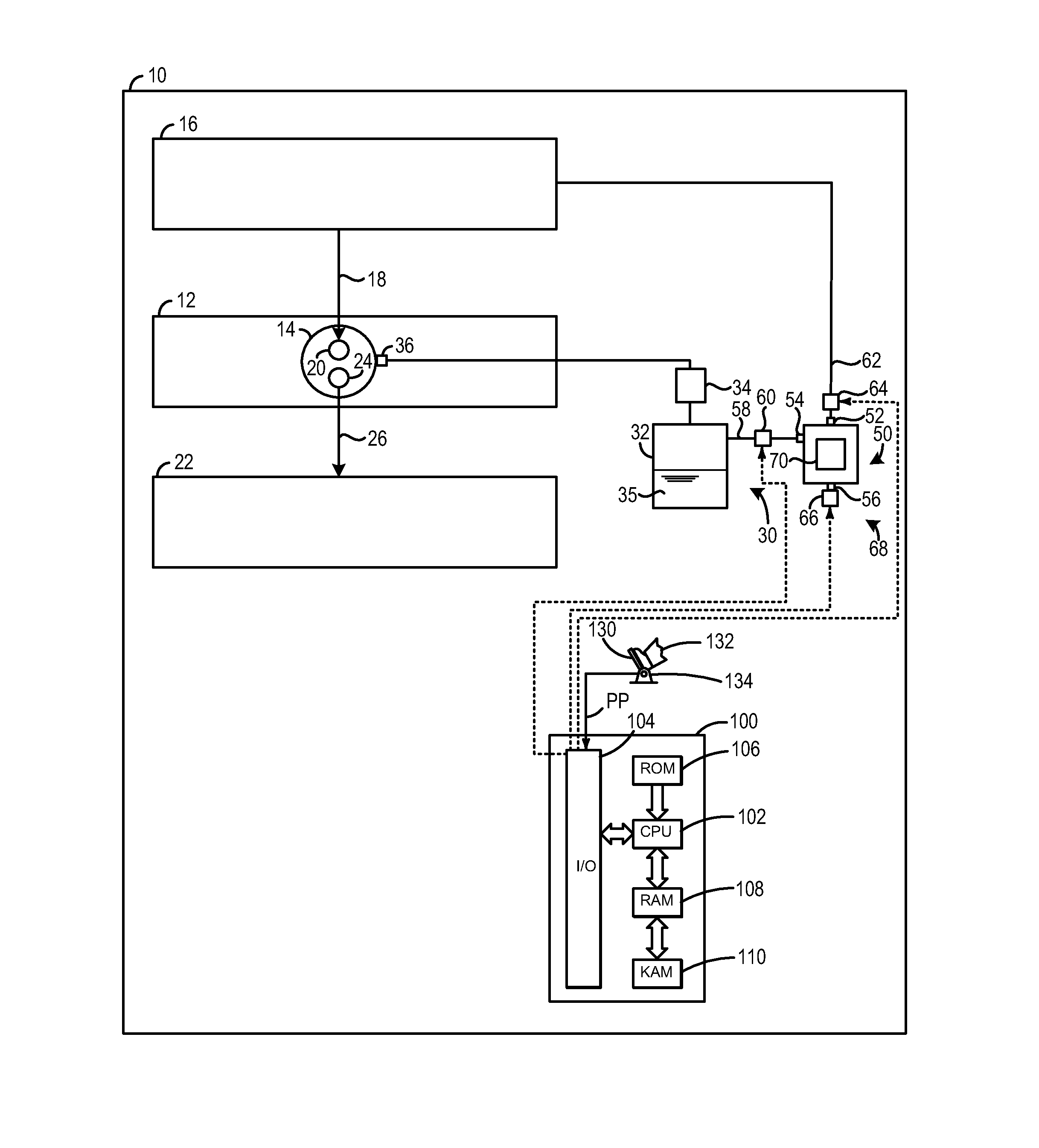
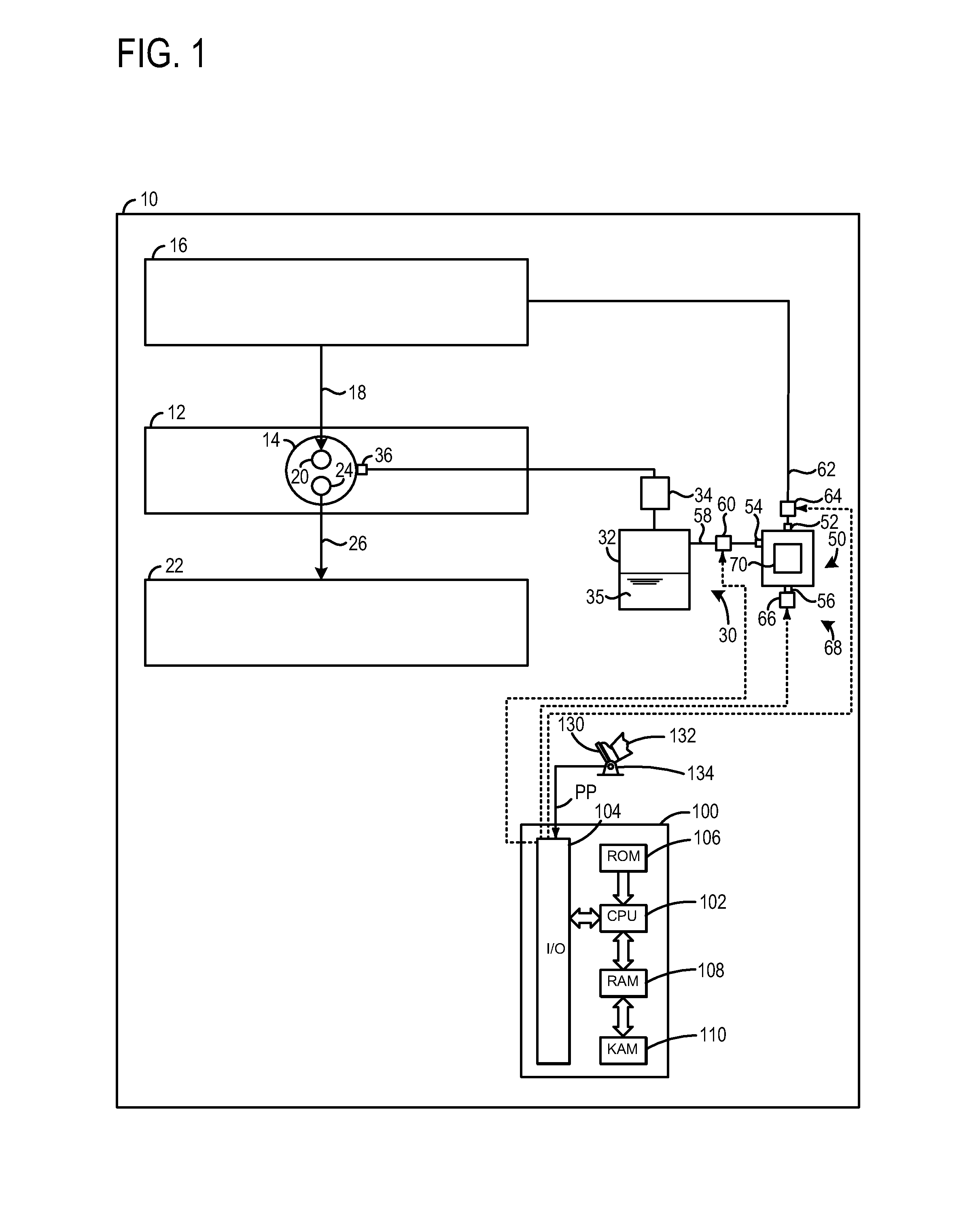
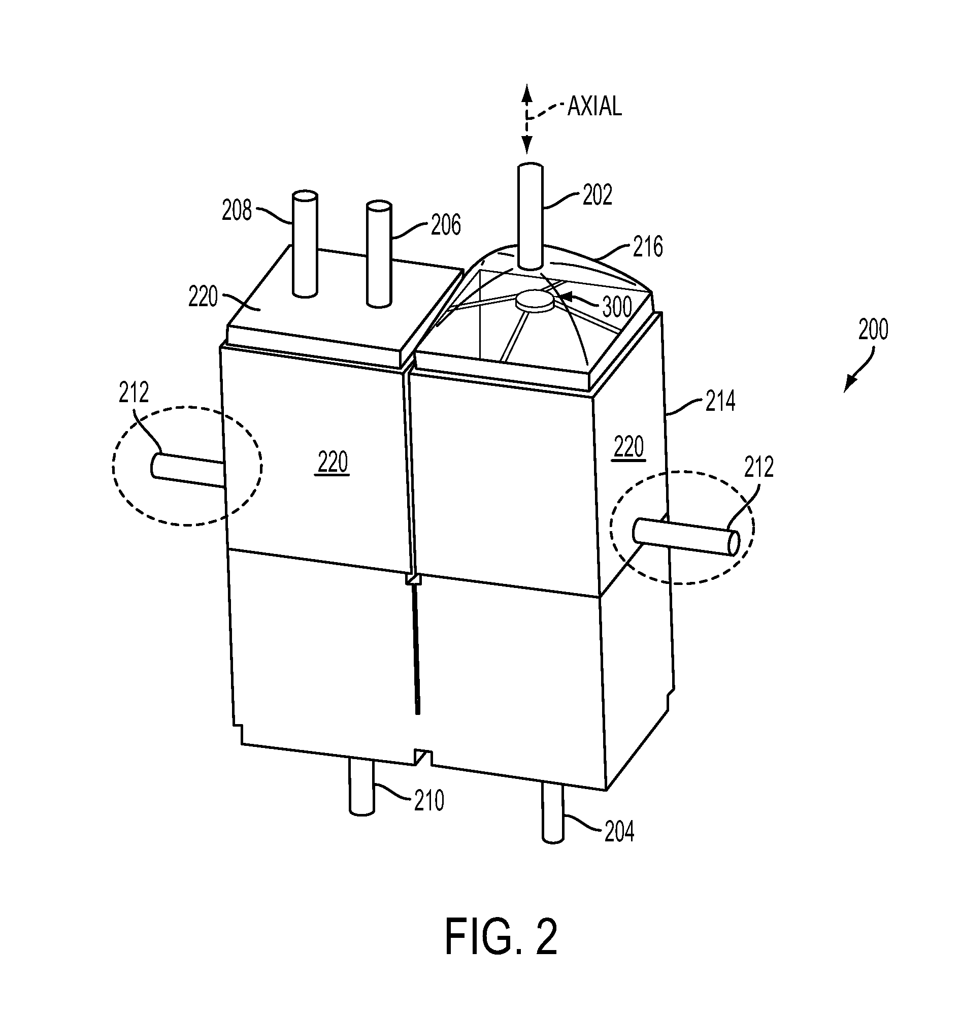
[0016]A vapor storage device is described herein. A dome and a diffuser plate in the device enables fresh air to be introduced into the device at a high flowrate while maintaining a high desorption rate of fuel vapor into the air passing through the device via an improvement in the distribution of airflow throughout the device. Specifically, the diffuser plate spreads flow around it but also let's metered quantity of air flow through into its wake for improved flow distribution, thereby increasing the amount of fuel vapor which may be desorbed in the device. As a result, air may be introduced into the device at a high flowrate during purging without unduly increasing the pressure drop across the vapor storage device during purge operation, thereby decreasing losses in the device. As a result, the vapor storage device may be purged in a small period of time. This may be particularly useful in vehicles which may have a small window for purge operation, such as hybrid type vehicles. Th...


PUM


Abstract

A vapor storage device is provided. The vapor storage device includes a diffuser plate positioned on an axis of an inlet port and comprising one or more openings extending through the plate from a leading edge to a trailing edge and a dome coupled to the inlet port of the device and the diffuser plate, where the dome includes side walls spaced away from the diffuser plate.

Description

FIELD[0001]The present disclosure relates to a vapor storage device and method for operation of a vapor storage device in a vehicle system.BACKGROUND AND SUMMARY[0002]Vapor storage canister, such as carbon canisters, are used in vehicles to reduce vapor emissions caused by temperature changes in the vehicle. For instance, temperature shifts in the fuel tank which may be caused by diurnal cycles, heat rejection from underbody components such as exhaust pipe and / or hot return fuel from engine can generate fuel vapors in the fuel delivery system. Fuel vapor is also generated during refueling because of air entrainment with liquid fuel, turbulence and temperature difference between tank fuel and fresh fuel. Furthermore for hybrid vehicles, fuel tank is sealed at high pressure. This pressure is released rapidly during refueling. This pressure change can also cause vapor generation. The fuel vapors may leak or permeate from the fuel tank if not properly sequestered. Therefore, in some veh...

Claims


Application Information

Patent Timeline
IPC IPC(8): B60K15/04B60K15/03
CPCB60K15/04B60K15/03006B01D53/04F02M25/0854F02M25/08
Inventor DONG, MIKEKRAGH, NIELS CHRISTOPHERHEIM, MICHAEL G.VAISHNAV, DHAVAL P.USMAN, MOHAMMAD
Owner FORD GLOBAL TECH LLC
Why Eureka
Try Eureka