

EVAP system with valve to improve canister purging
- Summary
- Abstract
- Description
- Claims
- Application Information
AI Technical Summary
Benefits of technology
Problems solved by technology
Method used
Image

Examples
Embodiment Construction
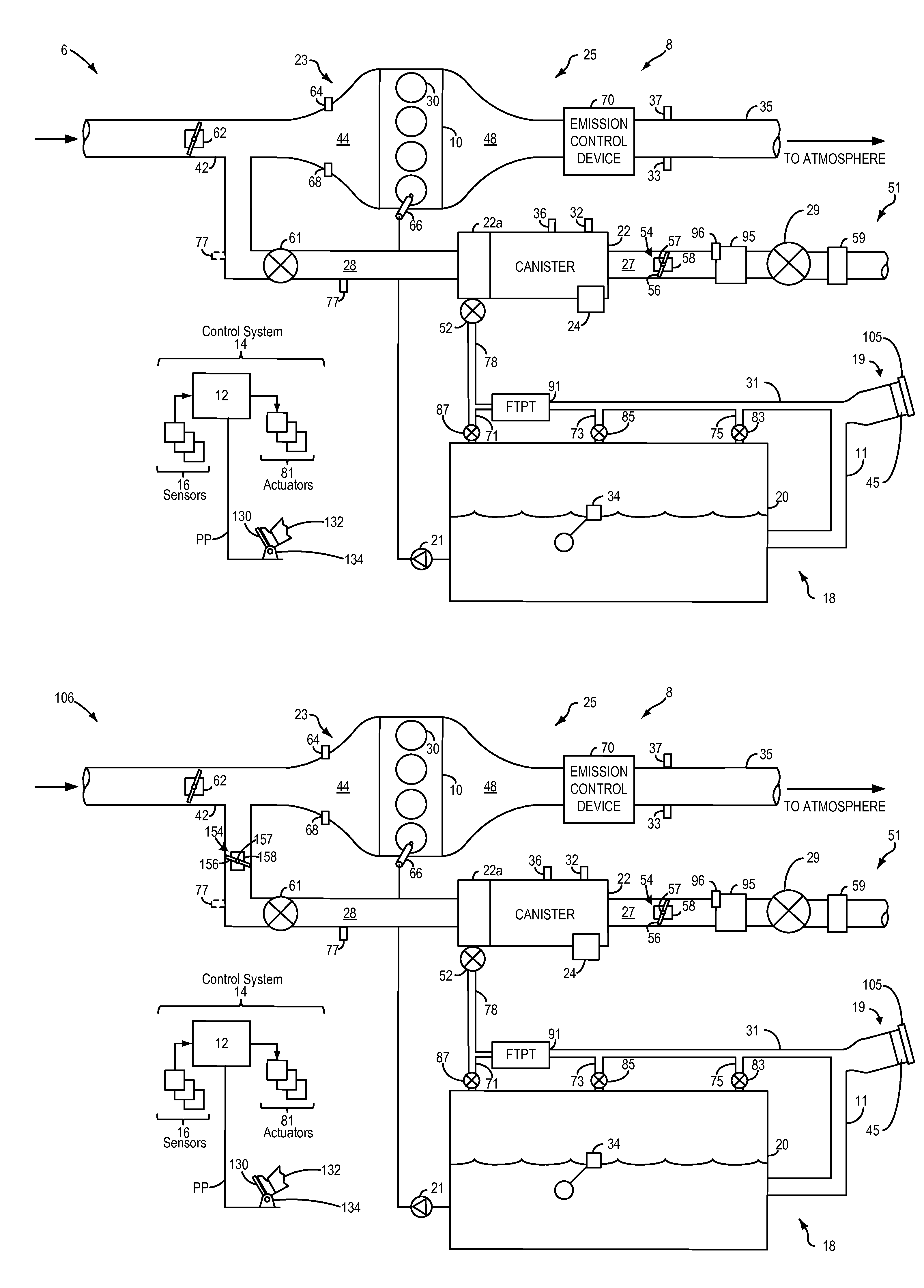
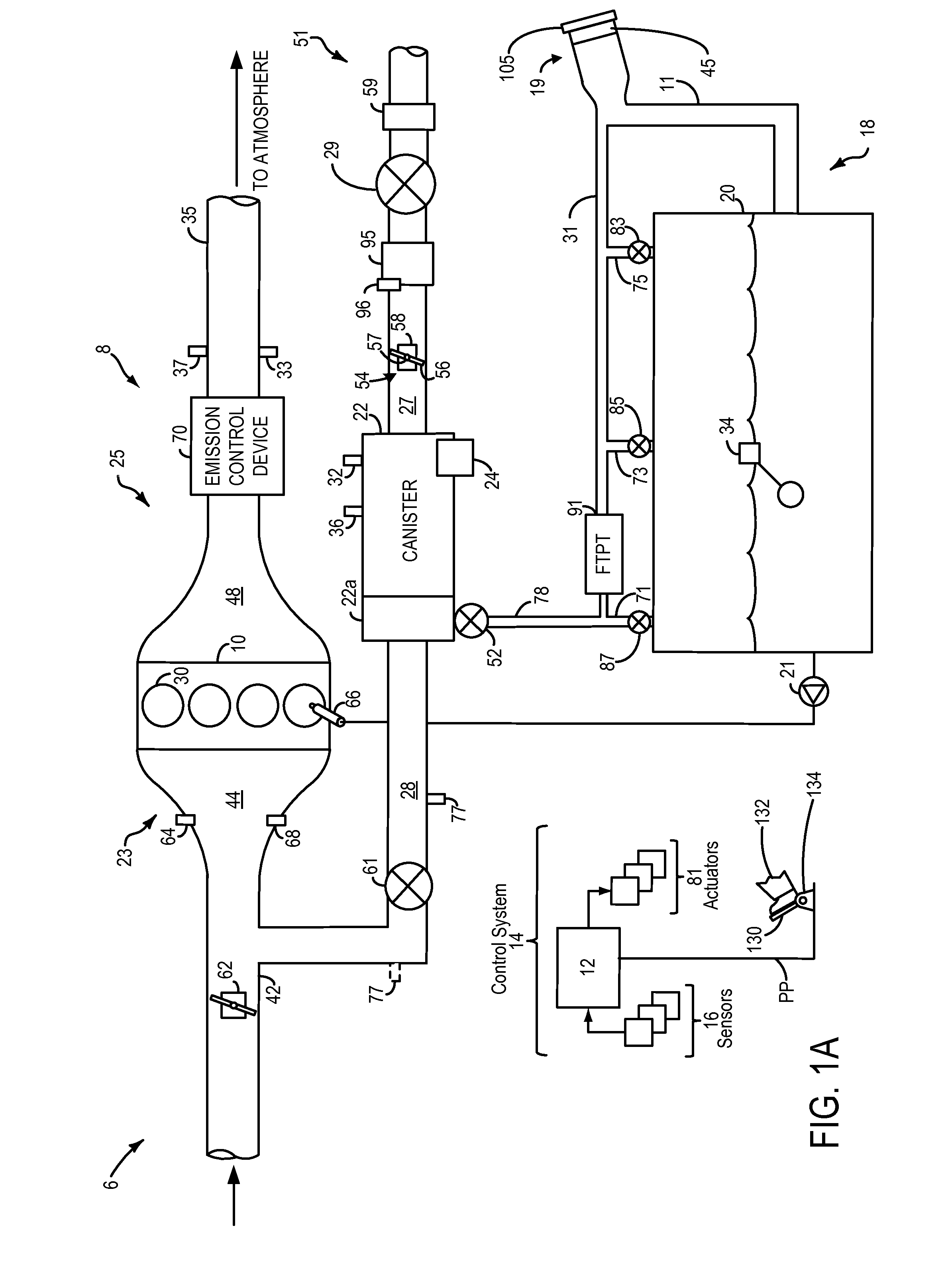
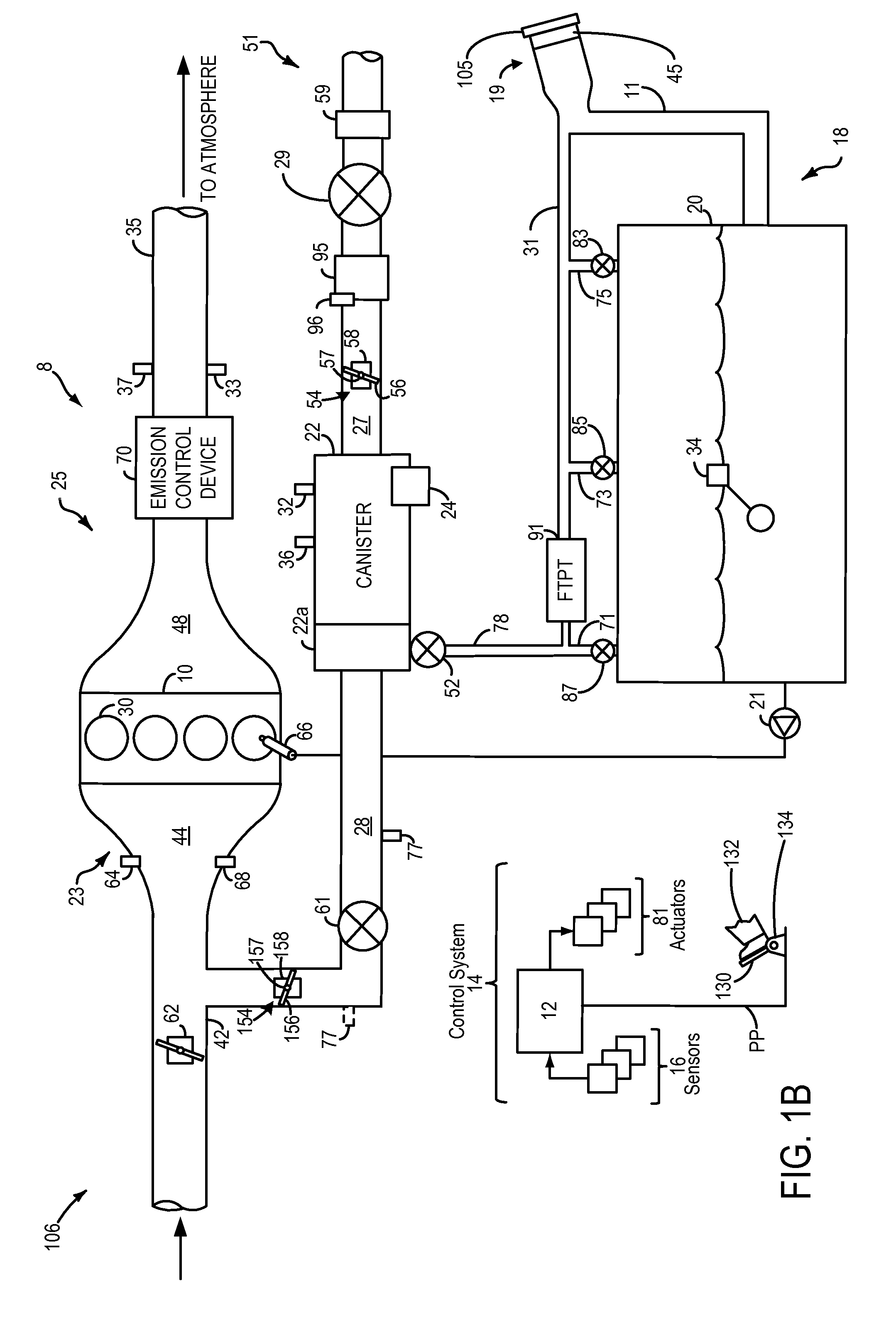
[0015]The following detailed description relates to systems and methods for improving purging of a fuel vapor canister included in an engine system, such as the engine system of FIGS. 1A and 1B. The fuel vapor canister may be coupled to an engine intake via a canister purge valve. Stored fuel vapors in the fuel vapor canister may be purged to the intake by opening of the canister purge valve, and a canister vent valve. Thus, during purging operation of the canister, the purge valve and vent valve may be opened to allow fresh, ambient air to be drawn through the canister via vacuum generated in an intake manifold. As air flows through the canister, it may come into contact with fuel vapors stored in the canister, and may cause the fuel vapors to be desorbed and purged from the canister.
[0016]However, airflow through the canister may be uneven. Thus, air flowing through the canister may be restricted to only a portion of the canister, and air may not reach all areas of the canister du...
PUM
 Abstract
Description
Claims
Application Information