Thermal insulation of a membrane module for mitigating evaporative fuel emissions of automobiles

a technology of evaporative fuel and membrane module, which is applied in the direction of machines/engines, separation processes, transportation and packaging, etc., can solve the problems of hydrocarbon air pollution, achieve the effect of reducing the dimension of the carbon canister, and reducing the number of carbon canisters

Active Publication Date: 2021-06-10
MAHLE INT GMBH
View PDF0 Cites 0 Cited by
  • Summary
  • Abstract
  • Description
  • Claims
  • Application Information

AI Technical Summary

Benefits of technology

[0003]One general aspect of the present disclosure includes a thermal insulation system for mitigating evaporative fuel emissions of an automobile, including a membrane component, and a thermal component connected to the membrane component, where the thermal component is configured for condensing fuel vapor generated from a fuel tank of an automobile. Due to the condensation of the fuel vapor, a smaller amount of fuel vapor will need to be adsorbed by a carbon canister (when a carbon canister is included in the automobile) and a smaller amount of fuel vapor will need to be separated by the membrane component, thereby reducing the number of the carbon canisters and the membrane components and reducing the dimension of the carbon canister and the membrane component needed to effectively reduce the fuel vapor emissions even in a surrounding environment with a high temperature.

Problems solved by technology

Evaporation of gasoline fuel from motor vehicle fuel systems is a major potential source of hydrocarbon air pollution.

Method used


Image

  • Thermal insulation of a membrane module for mitigating evaporative fuel emissions of automobiles
  • Thermal insulation of a membrane module for mitigating evaporative fuel emissions of automobiles

Examples


first embodiment

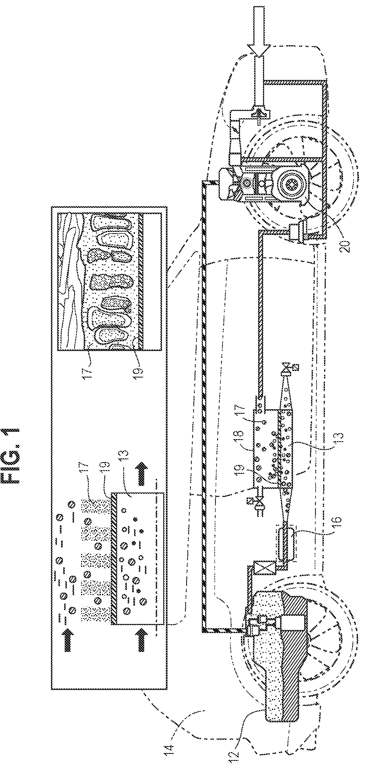
[0015]Referring to FIG. 2, the thermal insulation system 10 is shown. While the thermal insulation system 10 is shown to be directly connected downstream to the fuel tank 12, it will be appreciated that the whole system shown in FIG. 2 may be modified to include one or more carbon canisters connected between the fuel tank 12 and the thermal insulation system 10, disposed downstream of the fuel tank 12 and upstream of the thermal insulation system 10 for adsorbing at least a portion of the fuel vapor flowing out of the fuel tank 12.

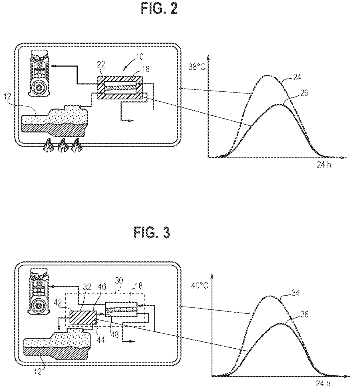
[0016]As shown in FIG. 2, the thermal insulation system 10 includes a thermal component 22 connected to a membrane component 18 (e.g., the thermal component 22 is disposed around the membrane component 18), such that a membrane component temperature change 26 (e.g., temperature increase) of the membrane component 18 is slower than an environment temperature change 24 (e.g., temperature increase) of a surrounding environment (e.g., an environment where the ...

second embodiment

[0020]Referring to FIG. 3, the thermal insulation system 30 is shown, which includes a thermal component 32 disposed upstream of (e.g., connected upstream to) a membrane component 18. As shown in FIG. 3, the thermal component 32 is connected downstream to a fuel tank 12 and configured for allowing at least a portion of the fuel vapor generated from the fuel tank 12 to flow into the thermal component 32 through a first inlet 42, flow out of the thermal component 32 through a first outlet 46, and then flow into the membrane component 18 through a second inlet 48. While the thermal insulation system 30 is shown to be directly connected downstream to the fuel tank 12, it will be appreciated that the whole system shown in FIG. 3 may be modified to include one or more carbon canisters connected between the fuel tank 12 and the thermal insulation system 30 (e.g., between the fuel tank 12 and the thermal component 32), disposed downstream of the fuel tank 12 and upstream of the thermal insu...


PUM

PropertyMeasurementUnit
temperatureaaaaaaaaaa
vacuumaaaaaaaaaa
thermalaaaaaaaaaa

Abstract

A thermal insulation system for mitigating evaporative fuel emissions of an automobile may include a membrane component and a thermal component connected to the membrane component. The thermal component may be configured for condensing, in the membrane component or in the thermal component, fuel vapor generated from a fuel tank of an automobile.

Description

TECHNICAL FIELD[0001]The present disclosure relates to a thermal insulation system for mitigating evaporative fuel emissions of automobiles, and in particular, a thermal insulation system for fuel vapor emissions caused by an increase in temperature.BACKGROUND[0002]Evaporation of gasoline fuel from motor vehicle fuel systems is a major potential source of hydrocarbon air pollution. An increase in environmental concerns has continued to drive strict regulations of the hydrocarbon emissions from motor vehicles even when the vehicles are not operating.SUMMARY OF THE INVENTION[0003]One general aspect of the present disclosure includes a thermal insulation system for mitigating evaporative fuel emissions of an automobile, including a membrane component, and a thermal component connected to the membrane component, where the thermal component is configured for condensing fuel vapor generated from a fuel tank of an automobile. Due to the condensation of the fuel vapor, a smaller amount of f...

Claims


Application Information

Patent Timeline
Patent Type & Authority Applications(United States)
IPC IPC(8): F02M25/08B60K15/03B01D53/22B01D53/04
CPCF02M25/0854B60K15/03B01D53/229B01D2259/4516B01D2253/102B01D2257/702B01D2259/40086B01D53/04B01D53/22B01D2053/221B60K2015/03072B60K2015/0348B60K15/03504B60K2015/03514
Inventor EHLERT, THOMASGOMMEL, ACHIMVOLZ, MELANIEJACKSON, JOHNSTRENG, SIMON
Owner MAHLE INT GMBH
Why Eureka
Try Eureka