Hybrid cable with flat power conductors

a technology of power conductors and hybrid cables, which is applied in the direction of insulated conductors, flat/ribbon cables, cables, etc., to achieve the effect of reducing loop inductance, maximizing mutual inductance, and enhancing bend ability in a bend plane and/or twist flexibility

Active Publication Date: 2015-02-05
COMMSCOPE TECH LLC
View PDF8 Cites 12 Cited by
  • Summary
  • Abstract
  • Description
  • Claims
  • Application Information

AI Technical Summary

Benefits of technology

[0010]The effect of this random selection of the supply and return conductors 19 and 21 is that the proximity of a supply conductor 19 to its return conductor 21 is not controlled within the hybrid cable 15. This random proximity between the supply conductor 19 and the return conductor 21 causes at least two effects. First, the loop inductance is variable from a set minimum based on the construction of the cable to a maximum. Second, the mutual inductance between conductors of different circuits can vary in a similar manner.
[0022]These and other objects are accomplished by a cable which reduces loop inductance by changing the cross-sectional shape of the conductive elements of the power supply and return conductors to something other than the traditional circular cross sectional shape, e.g., to a thin generally rectangular shape. Alternatively or in addition, the present invention provides power supply and return conductors in a controlled paired arrangement, so that mutual inductance is maximized within a given power supply circuit, and minimized between the given power supply circuit and other power supply circuits within the cable. The return power supply conductor may optionally be sized for multiple power supply circuits, which arrangement may further reduce loop inductance and reduce crosstalk noise between different power supply circuits.

Problems solved by technology

The Applicant has appreciated drawbacks in the cables of the prior art, which supply power to multiple devices via multiple power supply and / or return conductors.

Method used


Image

  • Hybrid cable with flat power conductors
  • Hybrid cable with flat power conductors
  • Hybrid cable with flat power conductors

Examples


first embodiment

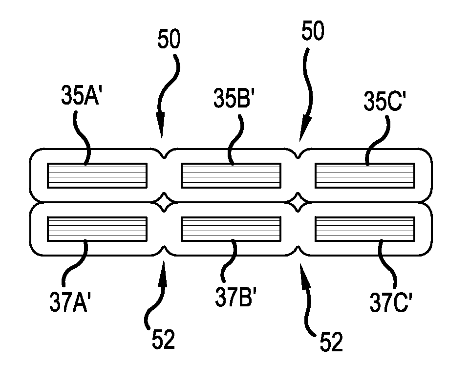
[0053]The outer jacket 33 surrounds a plurality of insulated power supply conductors 35 and a plurality of insulated power return conductors 37. In the first embodiment, the hybrid cable 31 includes first, second and third insulated power supply conductors 35A, 35B and 35C, and first, second and third insulated power return conductors 37A, 37B and 37C. The outer jacket 33 also surrounds a fiber optic cable 39. The fiber optic cable 39 may include numerous optical fibers and is but one embodiment of a communication signal carrying medium. Other types of communication signal carrying mediums may be employed such as coaxial cables and / or twisted pairs of insulated conductors.

[0054]In one embodiment, a shielding layer 38 may surround the plurality of insulated power supply and return conductors 35 and 37 and the fiber optic cable 39, with the outer jacket 33 surrounding the shielding layer 38. In a preferred embodiment, the conductive portions or current carrying portions of the plurali...

second embodiment

[0056]The outer jacket 43 surrounds a plurality of insulated power supply conductors 45 and a plurality of insulated power return conductors 47. In the second embodiment, the hybrid cable 41 includes first, second, third, fourth, fifth and sixth insulated power supply conductors 45A, 45B, 45C, 45D, 45E and 45F, and first, second, third, fourth, fifth and sixth insulated power return conductors 47A, 47B, 47C, 47D, 47E and 47F. The outer jacket 43 also surrounds first and second fiber optic cables 49A and 49B.

[0057]In one embodiment, a shielding layer 48 may surround the plurality of insulated power supply and return conductors 45 and 47 and the fiber optic cables 49, with the outer jacket 43 surrounding the shielding layer 48. In a preferred embodiment, the conductive center portions and the outer surfaces of the insulation layers of the plurality of insulated power supply and return conductors 45 and 47 are non-circular in cross section, such as generally rectangular in cross sectio...


PUM

PropertyMeasurementUnit
diameteraaaaaaaaaa
diameteraaaaaaaaaa
currentaaaaaaaaaa

Abstract

A cable reduces loop inductance by changing the cross-sectional shape of the conductive elements of power supply and return conductors to something other than the traditional circular cross sectional shape, e.g., to a thin generally rectangular shape. The power supply and return conductors are also controlled in placement along the length of the cable, so that mutual inductance is maximized within a given power supply circuit, and minimized between the given power supply circuit and other power supply circuits within the cable. The return power supply conductor may optionally be sized for multiple power supply circuits, which may further reduce loop inductance and reduce crosstalk noise between different power supply circuits within a common cable. The power supply and return conductors may be part of a hybrid cable used to power and communicate with plural remote radio units proximate a top of a tower.

Description

[0001]This application claims the benefit of U.S. Provisional Application No. 61 / 860,028, filed Jul. 30, 2013 and U.S. Provisional Application No. 61 / 897,779, filed Jan. 6, 2014, each of which is herein incorporated by reference.BACKGROUND OF THE INVENTION[0002]1. Field of the Invention[0003]The present invention relates to a power cable having insulated conductors to present at least one power supply. More particularly, the present invention relates to a cable, which includes a plurality of insulated supply and return conductors, wherein the cross sectional shapes of one or more of the conductors is rectangular, and wherein the power cable may be used in a hybrid cable for supplying power to equipment receiving communications via communication signal carrying mediums, such as optical fibers or conductive elements, e.g., coaxial cables or twisted pairs of conductors.[0004]2. Description of the Related Art[0005]FIG. 1 shows a cell tower 11 having a plurality of remote radio units (RR...

Claims


Application Information

Patent Timeline
Patent Type & Authority Applications(United States)
IPC IPC(8): H01B7/08H01B11/22
CPCH01B11/22H01B7/0823G02B6/4416G02B6/4435H01B9/005
Inventor HARWATH, FRANK A.ADAMS, SCOTT M.VACCARO, RONALD A.
Owner COMMSCOPE TECH LLC
Why Eureka
Try Eureka